Lightsail, 2024
405nm violet laser, Galvanometer, TouchDesigner, Phosphorescent Fabric, Fan
Exhibition: Ever-changing interference patterns glow on a shifting photoreactive sail
Exhibited at Tech25 in November 2024 and May 2025
Exhibited at Kirkland Gallery September 2025
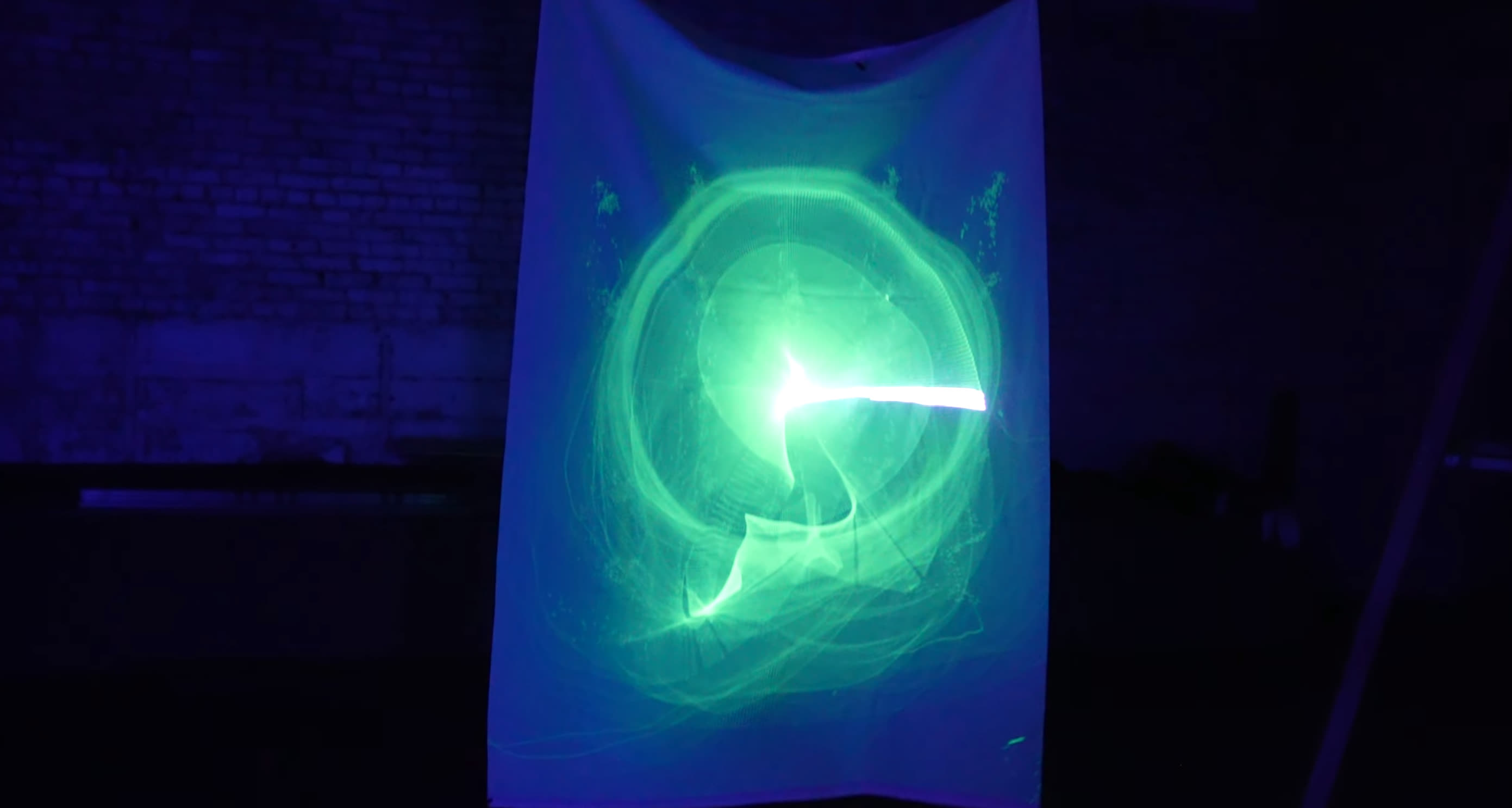
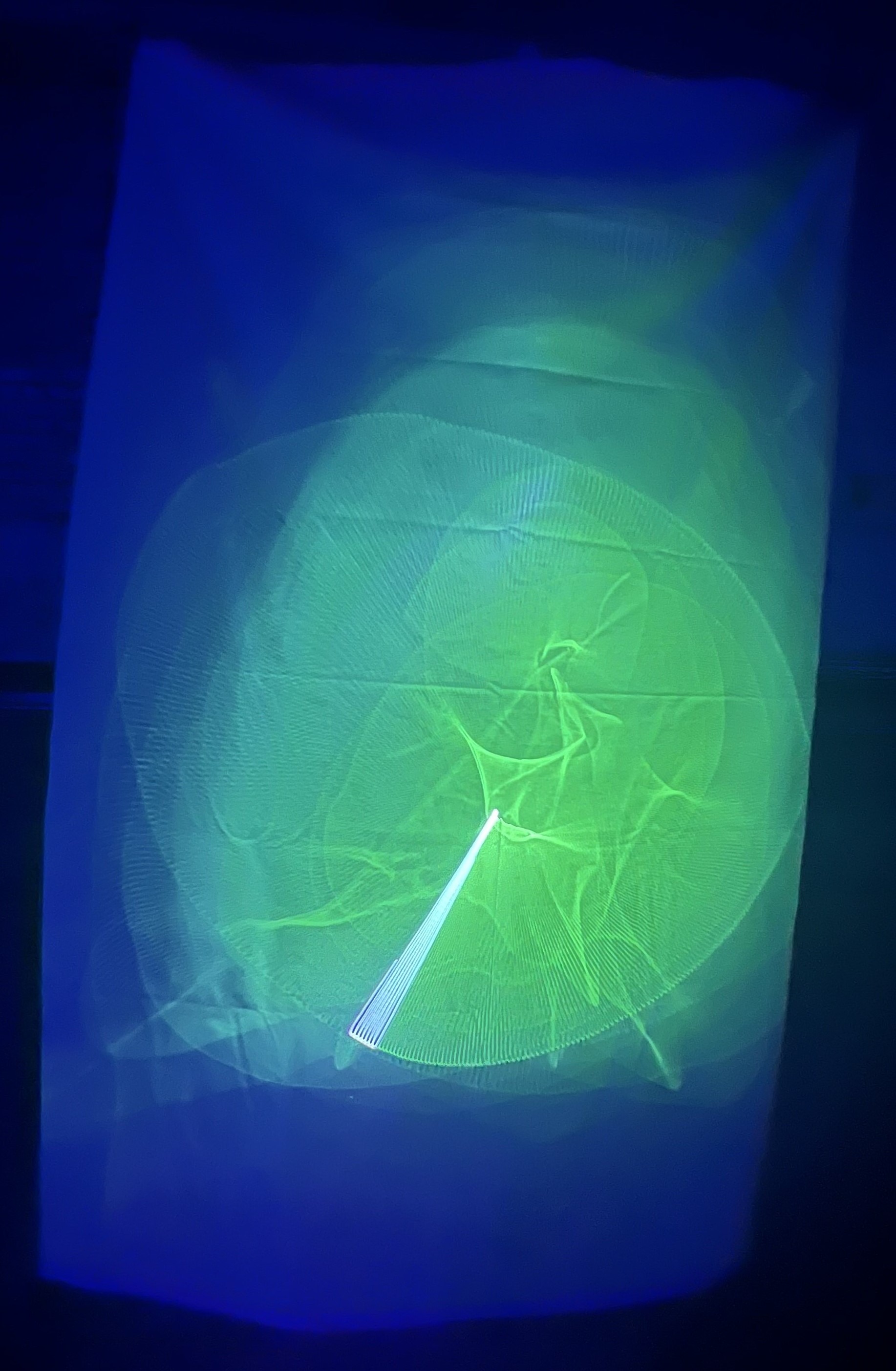
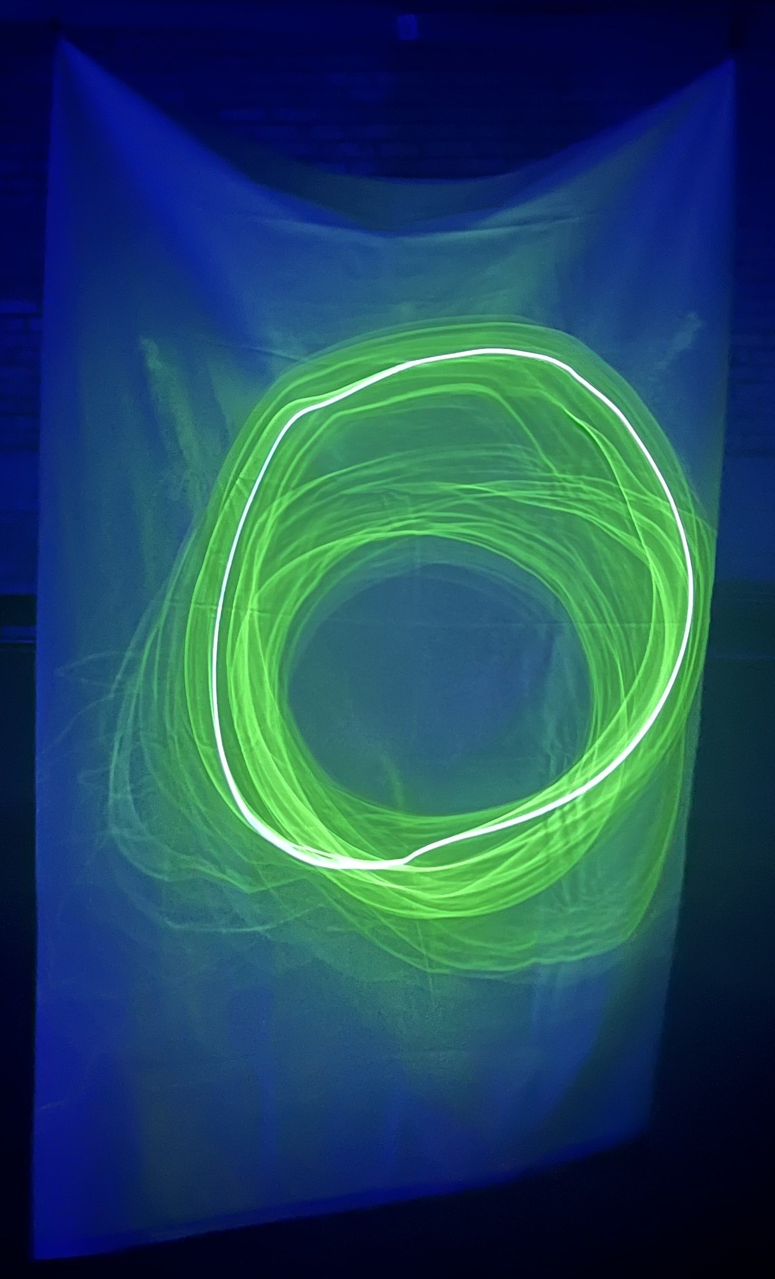
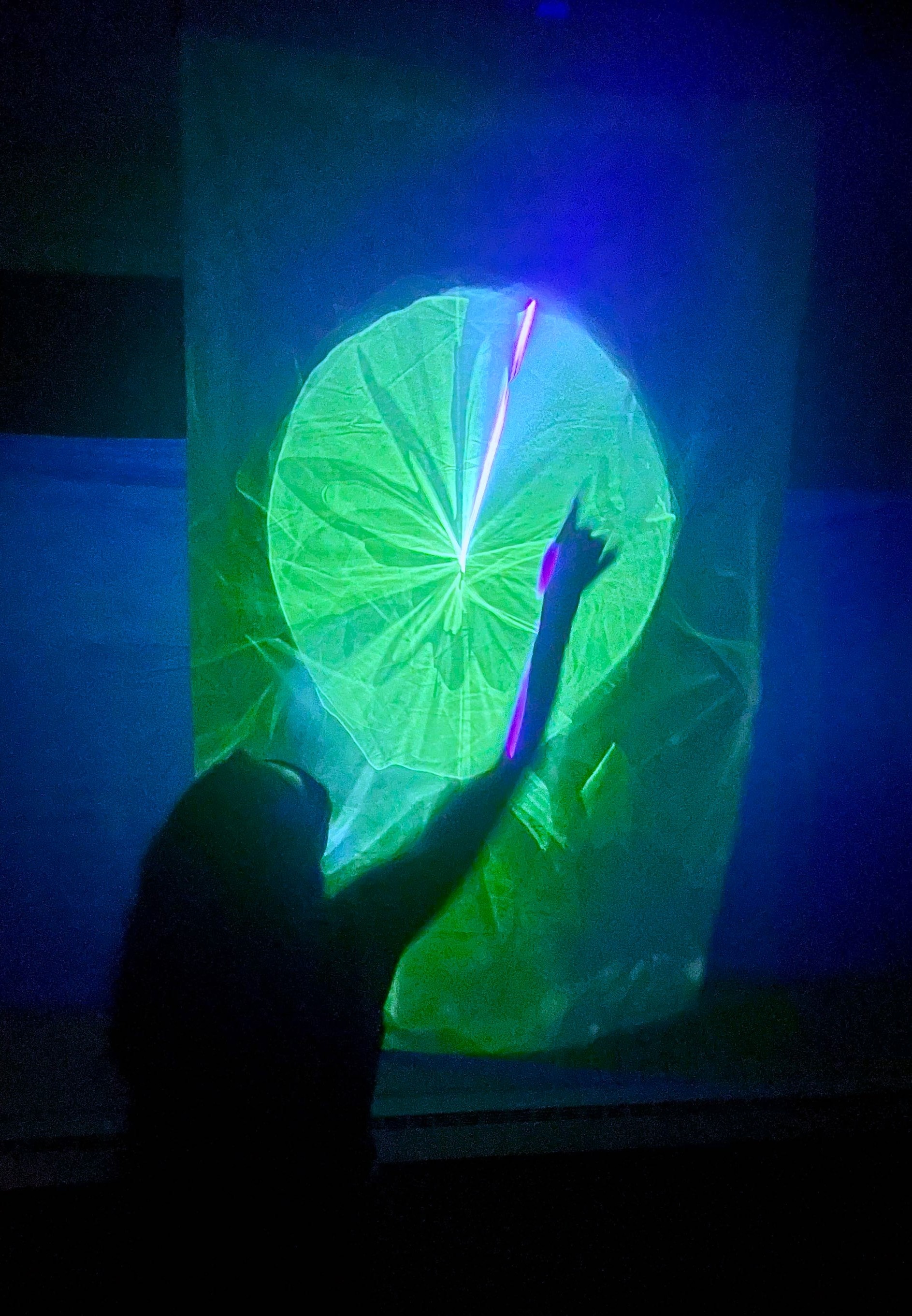
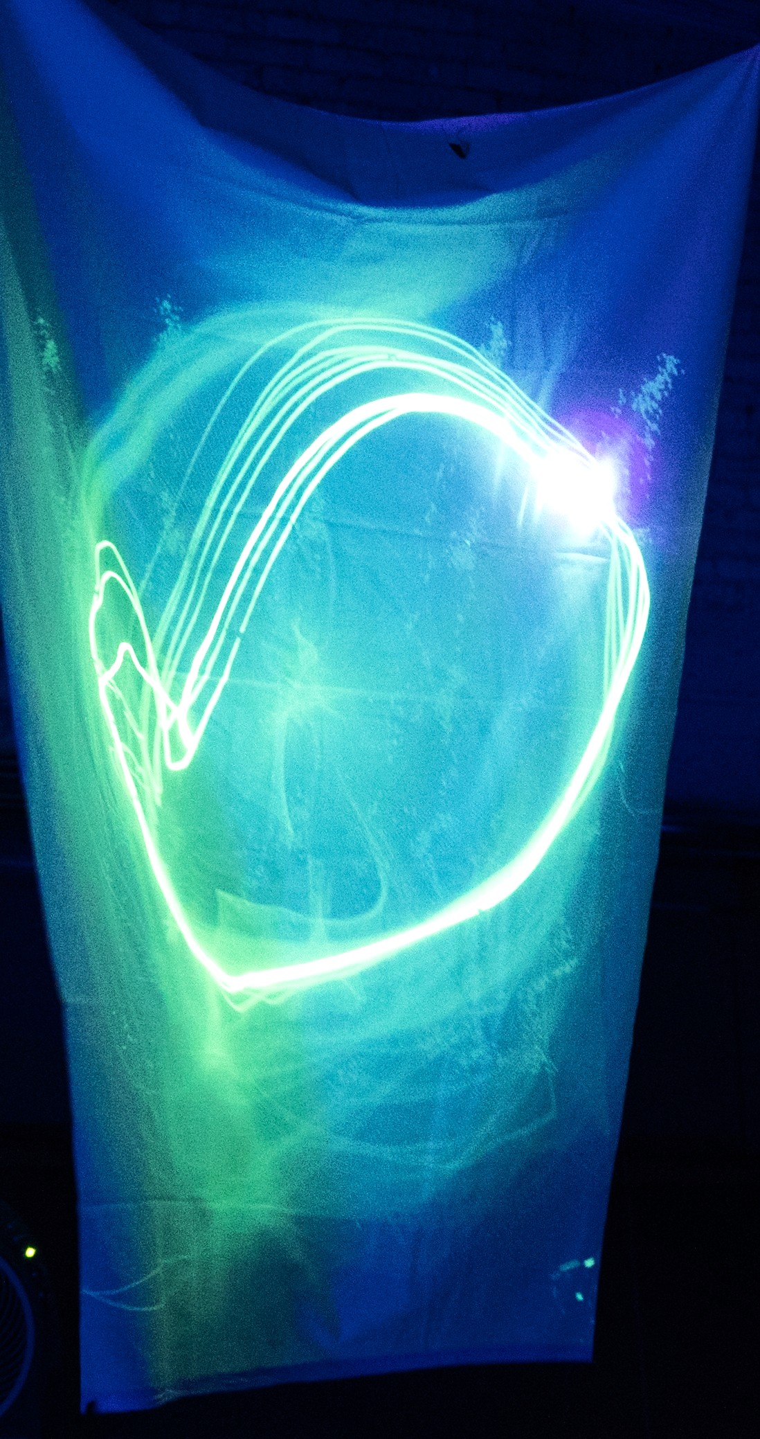
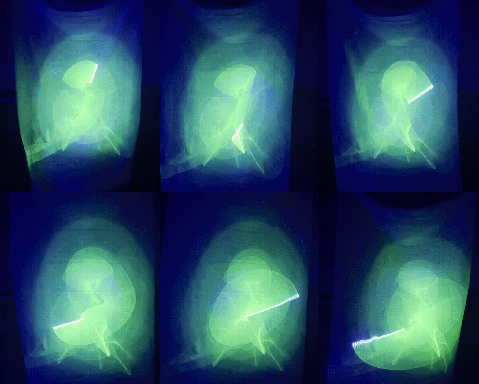
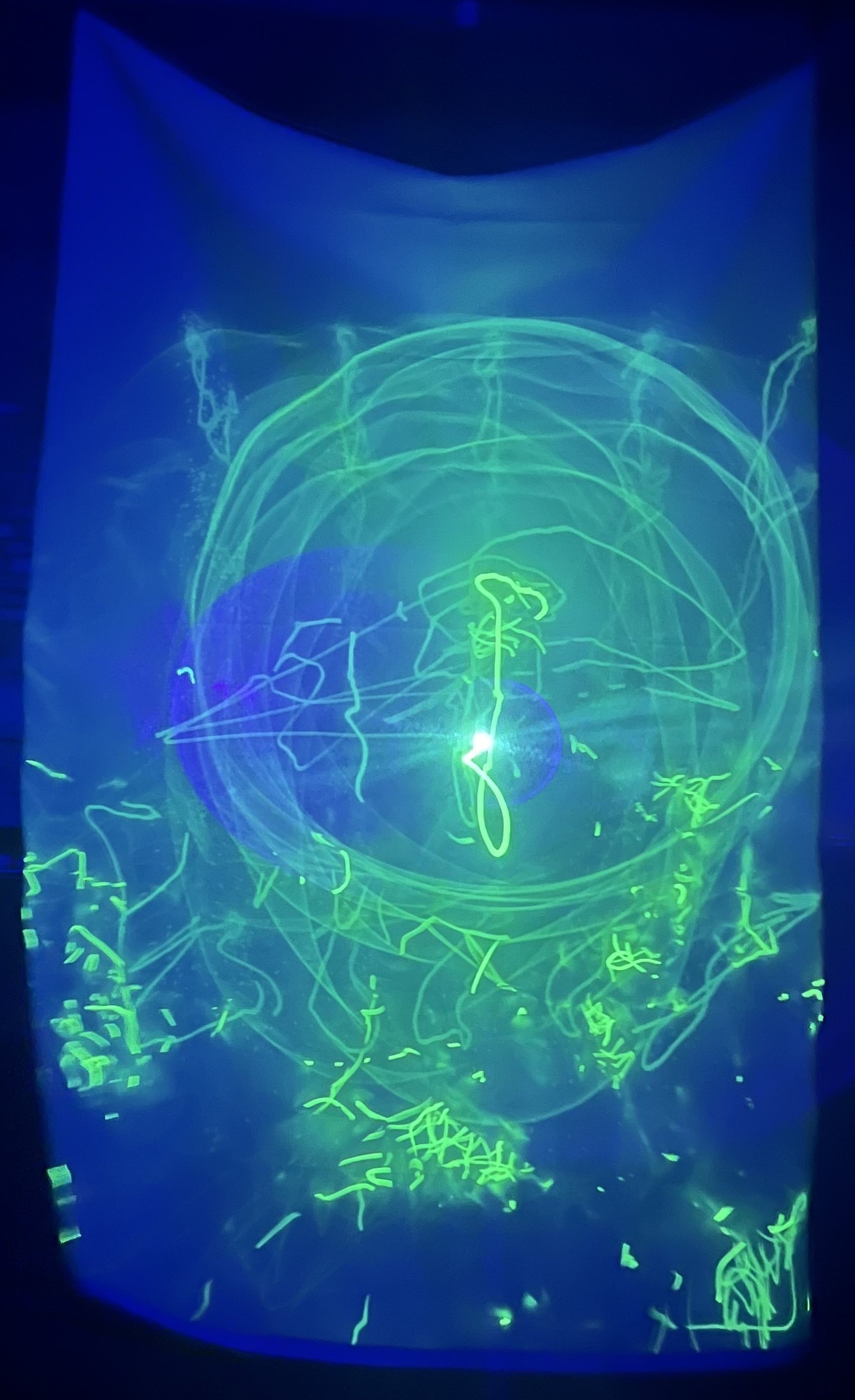
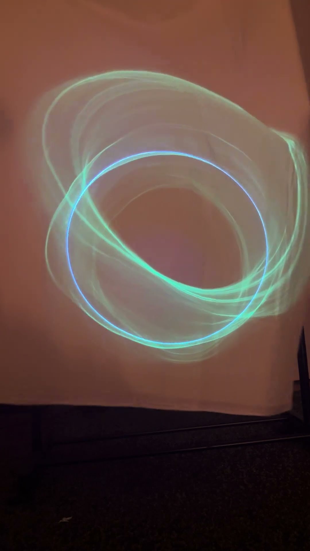
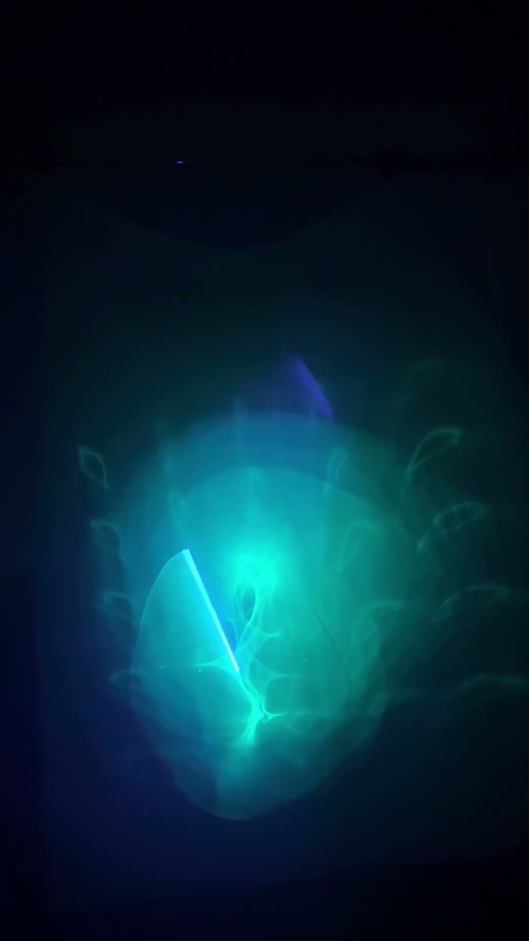
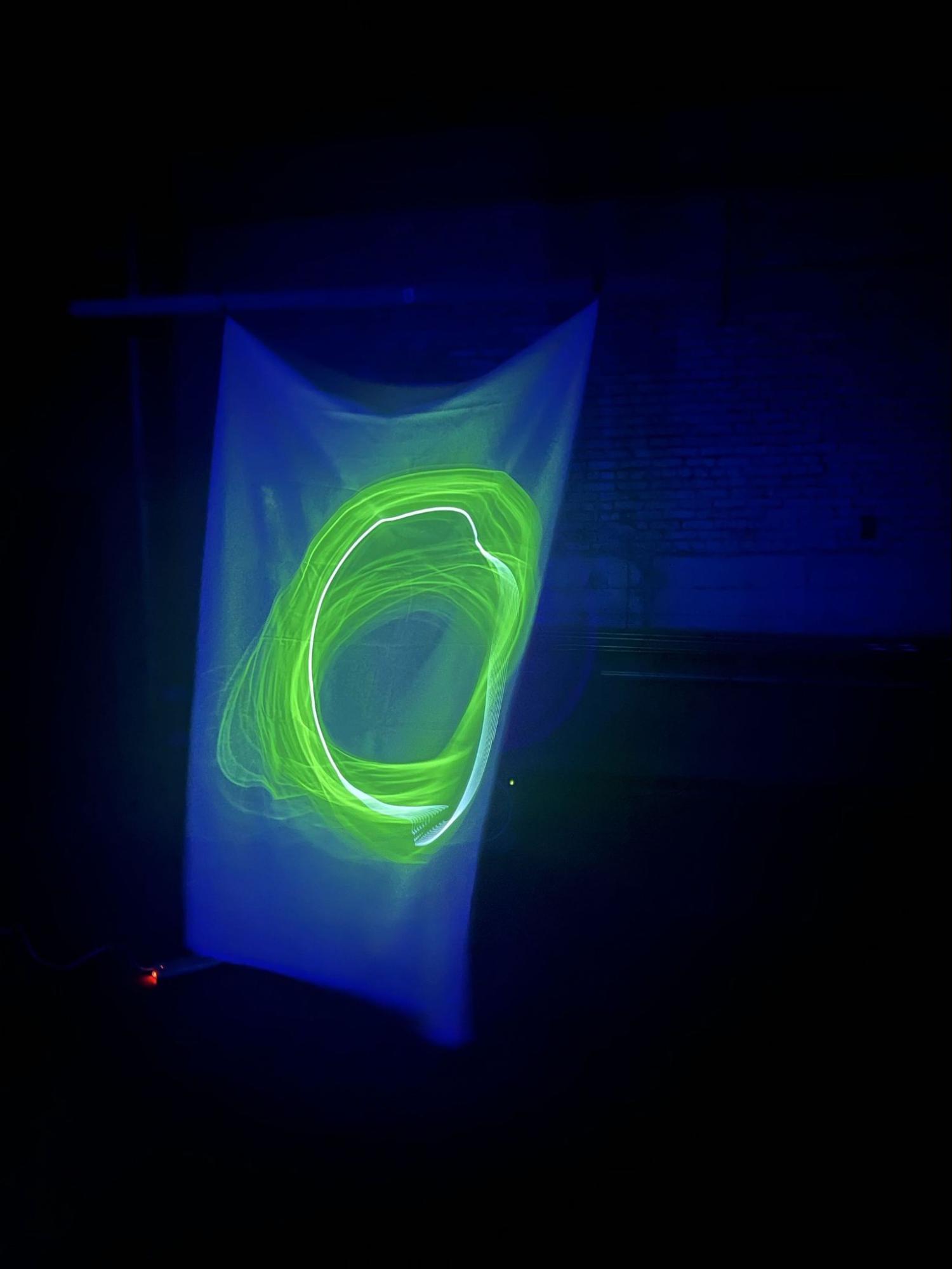
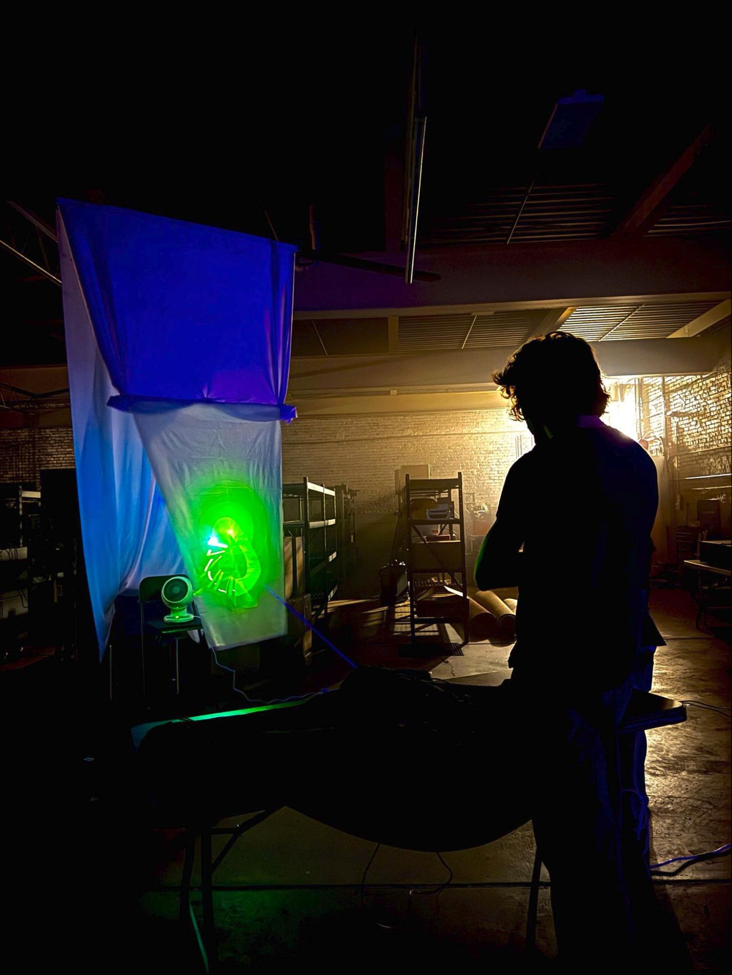
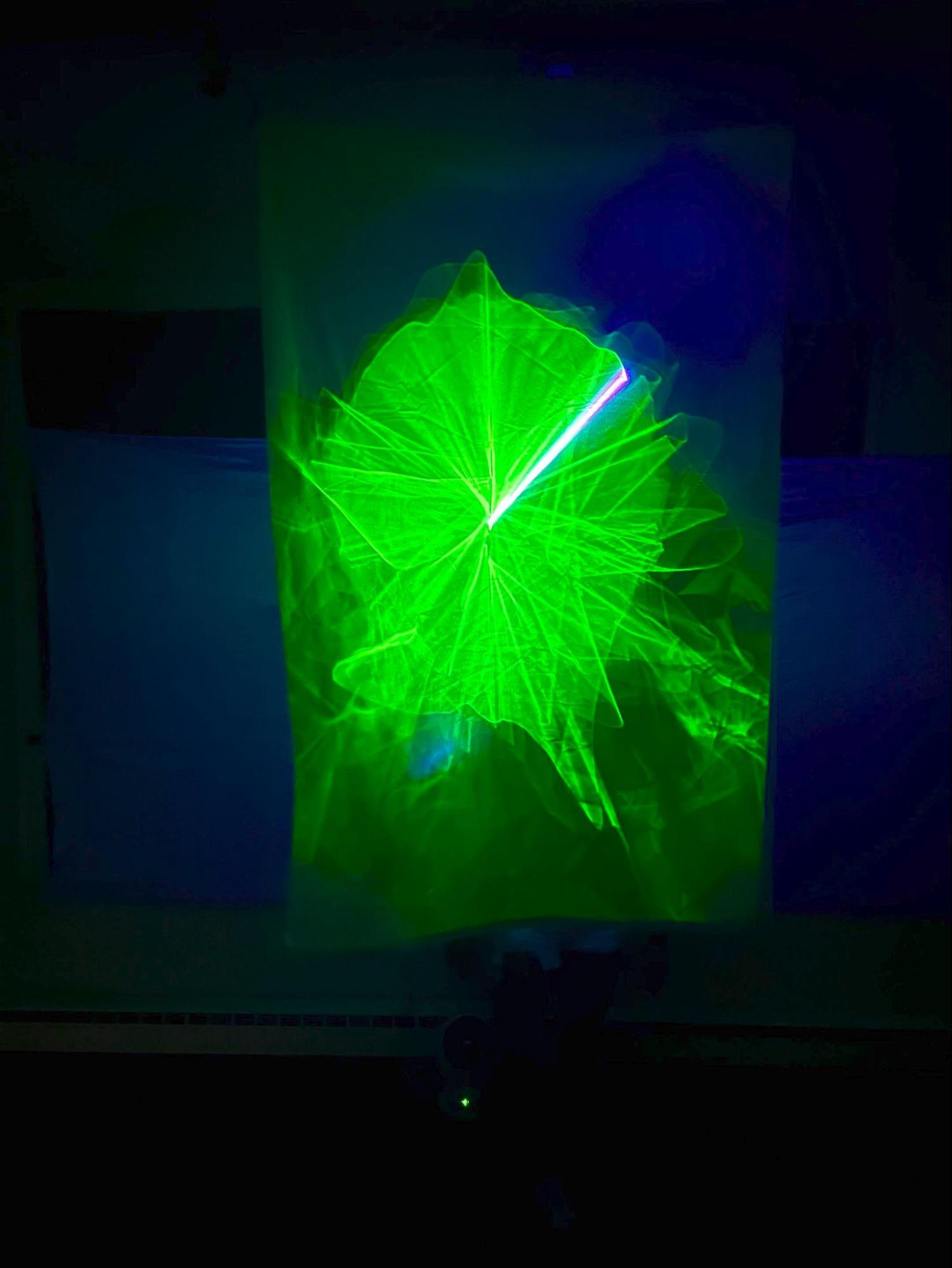
Inspired by Hans Haacke’s Blue Sail, this piece is a translation of the gusting irregularity of wind over time. Lightsail uses a custom-built galvanometer to project a 405 nm violet laser onto a phosphorescent sail fluttering in the wind of a fan. Controlled by programs I designed in TouchDesigner, the galvanometer rapidly moves the point of the laser, resulting in the illusion of continuous shapes. The phosphorescent sail is excited by the high energy light of the laser, causing it to glow wherever it is struck. This results in the sail fleetingly capturing a record of its own shifting motion as the wind changes the relative positions of the laser’s point and the sail.
Where the Idea Came From
August - September 2024
This project started from a now long-lost YouTube short I came across one day, of someone shining a laser pointer onto a sheet of phosphorescent paper. The laser point left a glowing trail behind it wherever its concentrated light excited the phosphorescent material, and that trail stayed lit for a few minutes.
I am always on the lookout for interesting physical interactions, and I have a particular interest in nontraditional drawing techniques. This checked both boxes. I noted it in the cool-ideas folder on my phone and got back to my day.
Over the following weeks I kept subconsciously turning the idea over, and around the same time I learned about the work of Hans Haacke, most of all Blue Sail - a blue chiffon veil suspended on fishing line with small weights, lifted and dropped by an oscillating fan underneath it.
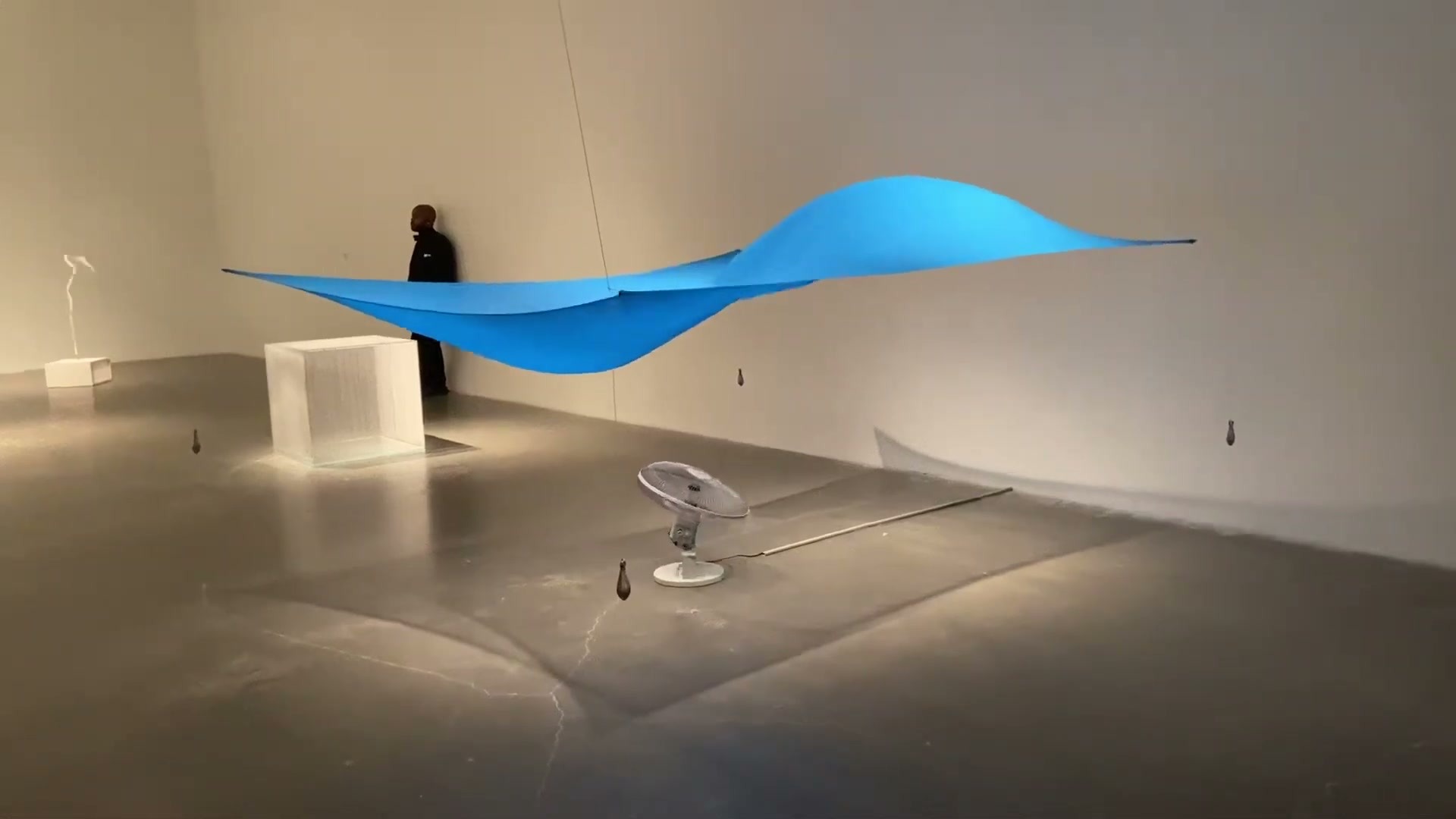
I hate to be cliche, but it really was a moment of inspiration: Blue Sail and the laser phosphorescence came together in my head, and I knew I had a new project. Blue Sail turns the wind into motion, and laser phosphorescence would let me draw with that motion.
V0: Proof of Concept
Early October 2024
The first version of the idea was simple. If I could make a phosphorescent sheet that blew around like Blue Sail did, then a stationary laser pointed at that sheet would record the sheet's motion relative to the fixed laser point. The wind moves the sail, the sail moves under the laser, and the glowing trail left behind records that motion.
Sourcing the parts
Both halves turned out to be cheap. You can buy glow in the dark fabric for very little off Amazon and at most local craft stores - the market for it appears to be mainly kids' Halloween costumes, with assorted other clothing crafts mixed in.
The laser was equally easy, with one compromise. Phosphorescent glow is best excited by ultraviolet light, but UV lasers are both more expensive and more dangerous, so I went instead for a 405 nm laser. At 405 nm it is technically deep violet rather than ultraviolet, sitting just at the edge of the UV band, but it is close enough to excite the phosphor well.
Does the glowing line work?
The first check was whether I could reproduce the effect I had seen in that short at all.
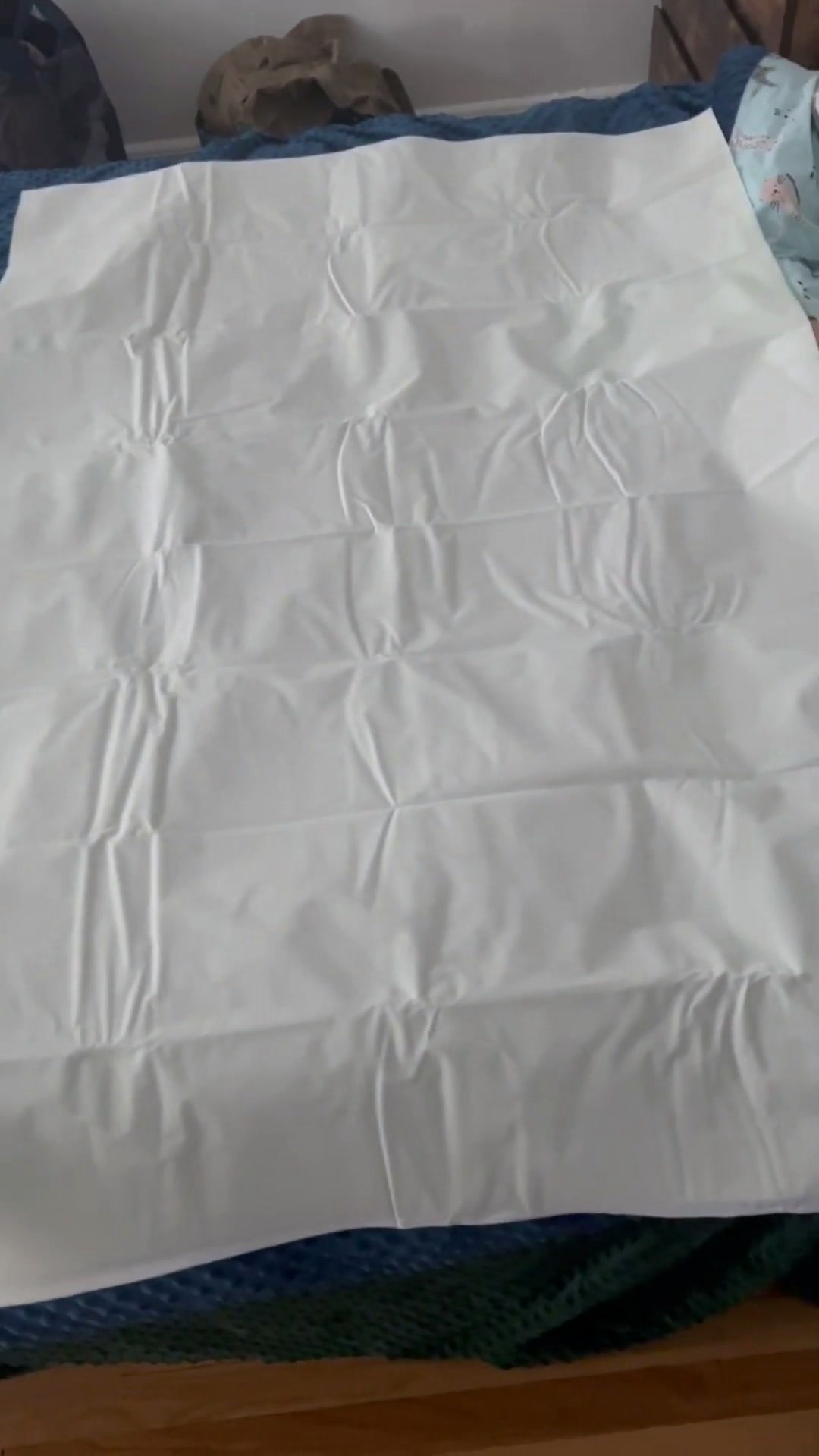
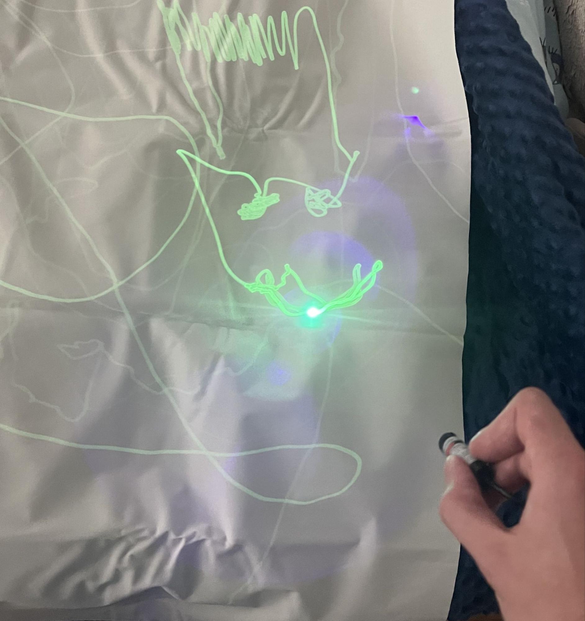
This turned out to be as simple as I could have hoped. Even in ambient daylight the glowing line was bright enough to stay visible for a good 30 seconds after it was drawn:
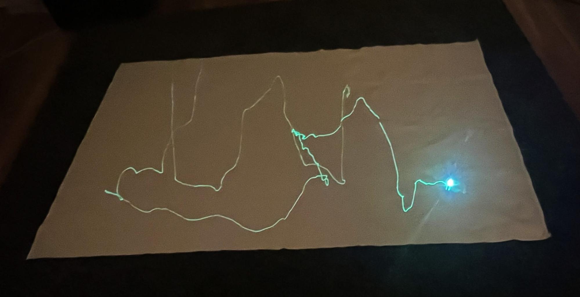
And it was vivid, lasting a number of minutes under darker conditions:
Adding the sail
With the phenomenon confirmed as practical, the next step was to bring in the Blue Sail side of the piece. I used a standard table fan I had lying around the house, and I moved the fabric from being suspended horizontally, as Blue Sail is, to hanging vertically. There were two reasons for that:
1.It was much easier and didn't sacrifice the concept. Blue Sail relies on a carefully tuned arrangement of fishing line and small weights to get its particular motion. That motion is beautiful, but my goal was a drawing made by the wind, so the specific layout of the sail mattered less.
2.The drawing is just as important to the piece as the sail itself. For the drawing to be visible, the sail, which functioned as its canvas, should be hung vertically to face the viewer.
Results
That gave me my first complete setup for making drawings with the wind: fan at the back blowing forward, sail hanging in the middle, laser at the front pointed at a single fixed spot on the sail:
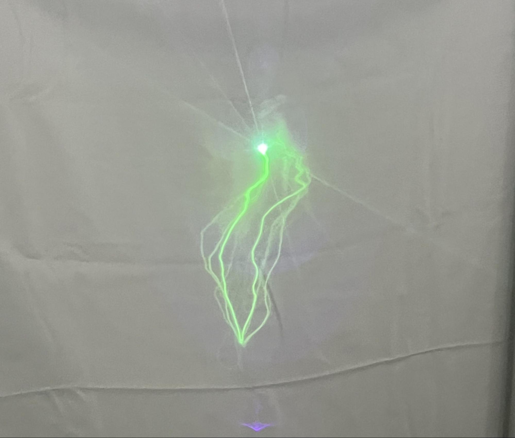
This also produced an effect I had not expected. There was a clear period to the sail's motion, showing up in the drawing as repeated closed circuits, and it appeared even when the fan's swivel mode was switched off. It seems to come from the sail billowing upward on the wind and then coasting back down once its upward inertia is overwhelmed by its own weight. Stable, non-chaotic behavior emerging from a chaotic system is one of my favorite things in the world, and this effect ends up being central to the rest of the project.
Limitations
As much as I liked it, this felt more like a demo of a few interesting interlocking phenomena than an actual artwork. By this point I knew I wanted to exhibit the piece at Tech25, an organization supporting video art and event production technology, and for an exhibition space like that it needed far more visual scale than one small glowing squiggle.
V1: Building a Laser Galvanometer
Late October 2024
Around this time I also happened to learn about laser galvanometers.
A galvanometer scanner is a limited-rotation motor with a mirror mounted on its shaft. Give it a voltage and it turns the mirror to a proportional angle. On its own that would be open-loop - you command an angle and hope the mirror gets there - which is not accurate enough at speed, so each scanner also has a position sensor built into the same housing, a small transducer on the shaft that continuously reports the mirror's actual angle. The driver reads that sensor, compares the real angle against the one you asked for, and adjusts the current to close the gap, thousands of times a second. That feedback loop is what lets the mirror snap to a new position and hold it. Mount two scanners on perpendicular axes and you can steer a single beam anywhere in a two-dimensional field: the first mirror sweeps the beam up and down, and the second one catches that beam and sweeps it from side to side.
Each mirror turns on its own axis, and the two are perpendicular. The Y mirror tilts within the plane of the page, moving the point up and down the sail; the X mirror turns about the gray shaft running through it, moving the point across. Three sampled beam positions are shown.
The speed is what makes them useful. Galvos are rated in points per second, and the set I ended up with is rated at 20,000. Anything redrawn faster than roughly 30 times a second stops reading as a moving dot and starts reading as a continuous line, so at those rates a galvo is effectively an extraordinarily fast light drawing machine.
That galvos are relevant to a project already built around a laser is obvious enough. What I specifically wanted was for the wind to have something more interesting to work against. Rather than the laser being a single stationary point, I wanted it to move, and to form shapes. That gave me two sources of drawing at once: the wind, which is chaotic and mostly outside my control, and the galvo, whose movement I control precisely and computationally.
The first thing I wanted to try was generating moiré patterns with the wind. Running the galvo at full speed with instructions to draw a circle sends the laser point around that circle roughly a hundred times per second. If the sail is moving while that happens, each circle lands in a slightly different place than the last, and the overlapping circles should produce a moiré.
Galvos are expensive
There was a big problem: even low-end programmable laser galvos start around $1,000, well out of budget for this project.
But there was a way around it. The hardest part of a laser galvo to construct is the pair of closed-loop galvanometer motors and the driver electronics that hold their position, and you can buy exactly those parts on Amazon for around $100, a fraction of the price of a finished unit.
Just a set of components
This was far from a perfect fix. What arrives really is only a set of components: completely unwired, with no instructions, and built solely to move the mirrors. No laser, and no way to interface with a computer.
This part of the project came at a convenient time. I had just had my wisdom teeth removed and had to stay inside for about a week to recover, which left me plenty of time to sit and tinker with galvo components.
I started by squinting at the product photos on Amazon and trying to reproduce the wiring from them. The real breakthrough was finding this tutorial on assembling a laser galvo. The components in it are not quite the same as the ones in my set, but it gave much-needed context to someone who had never worked with a galvanometer before.
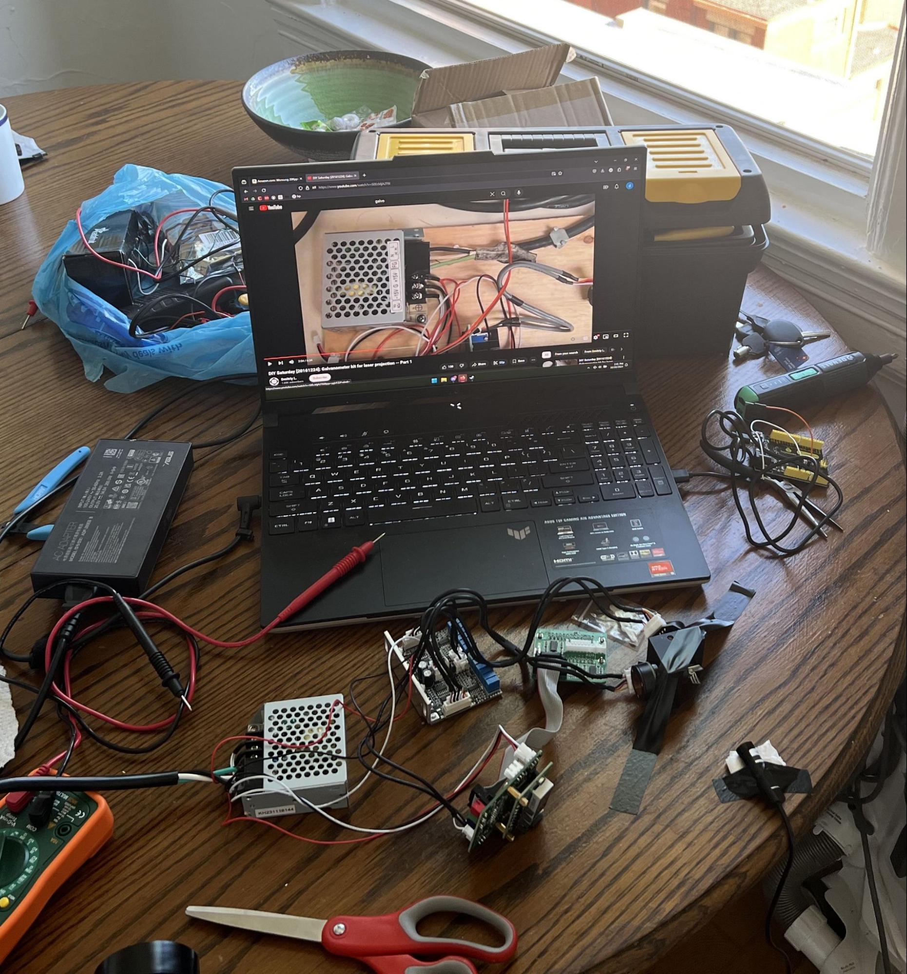
Eventually I got everything wired correctly and the mirrors moving.
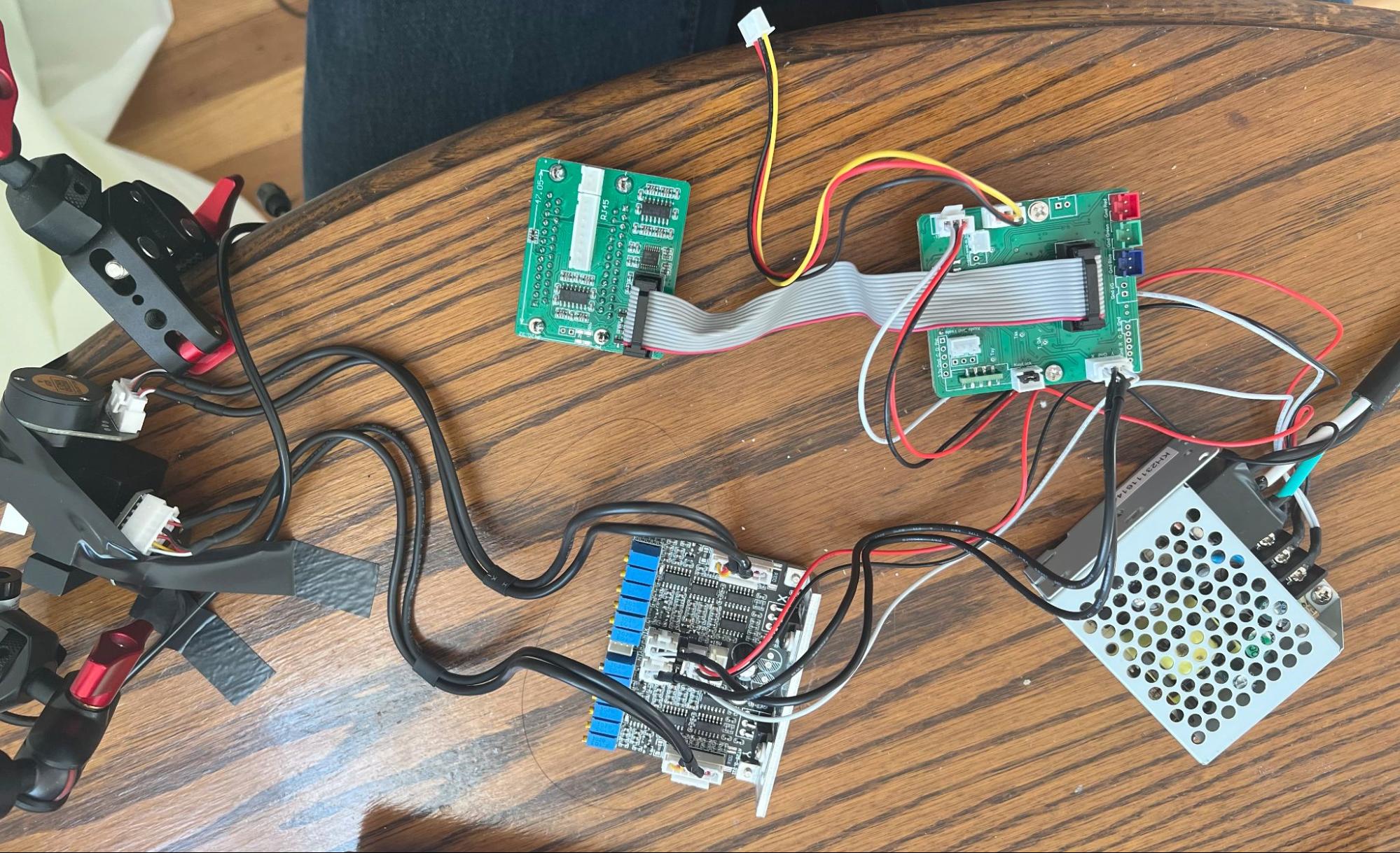
Since I still had no way to drive the galvo from my computer, I used the driver's own small internal library of preset patterns, selected with the DIP switches on the board. That worked, and once I lined my laser up with the mirrors I could see the galvo's test animation being projected across the room.
This is also the point where a limitation showed up: my laser is a laser pointer taped in place and aimed at the mirrors. A laser pointer takes power in and puts light out; it has no modulation input, so there is nothing on it that could receive a signal telling it to switch off. The galvo's control standard, ILDA, carries a channel for exactly that - blanking - but I had nothing that could listen to it.
The practical consequence is that everything I could draw had to be one continuous line. There was no way to 'lift the pen', which became relevant further down the line.
Overheating
Within about a minute of celebrating, I started to smell burning plastic. After some testing, I found that the aluminum heatsink on the motor driver was extremely hot, far past what was safe for the component.
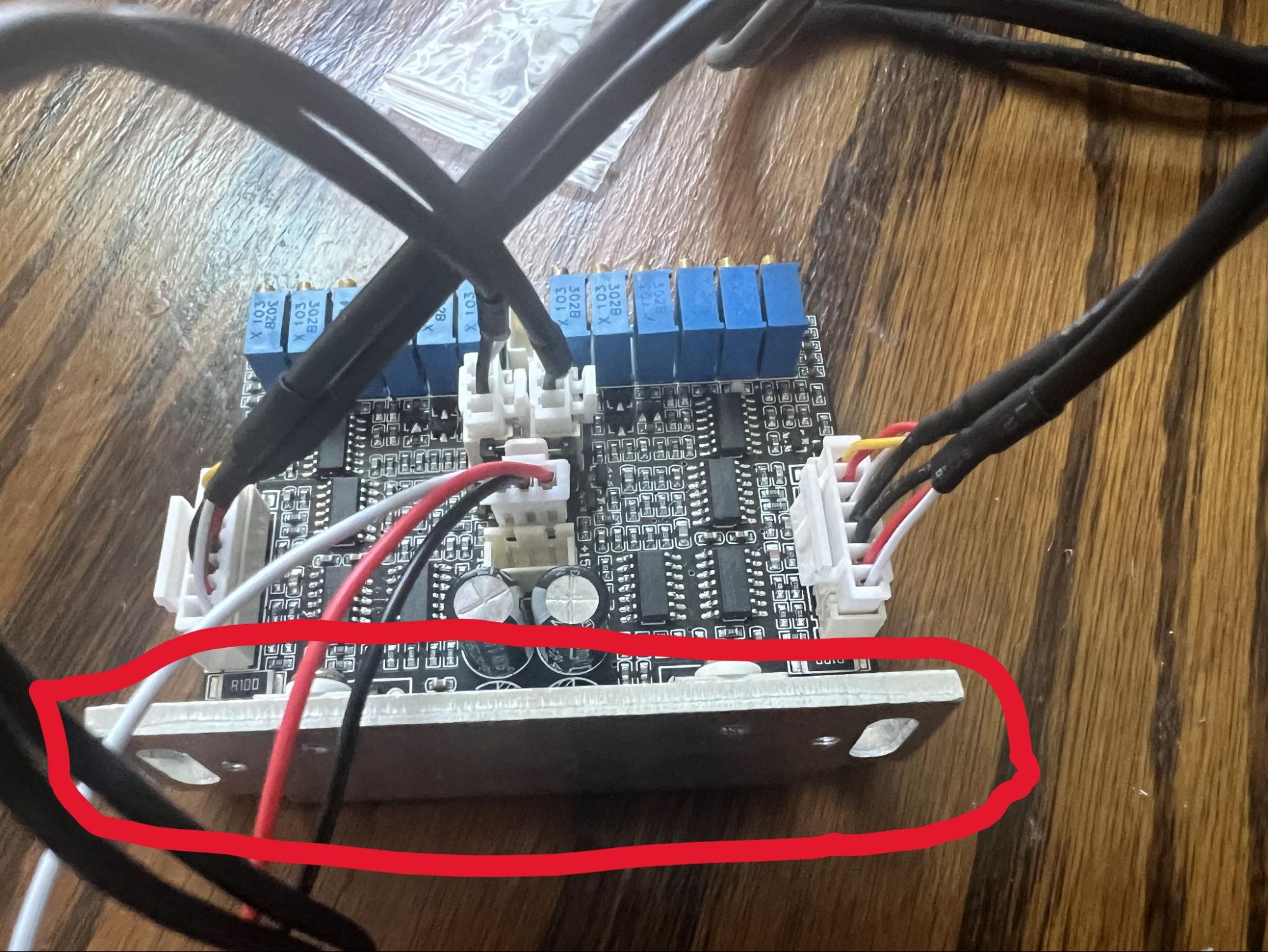
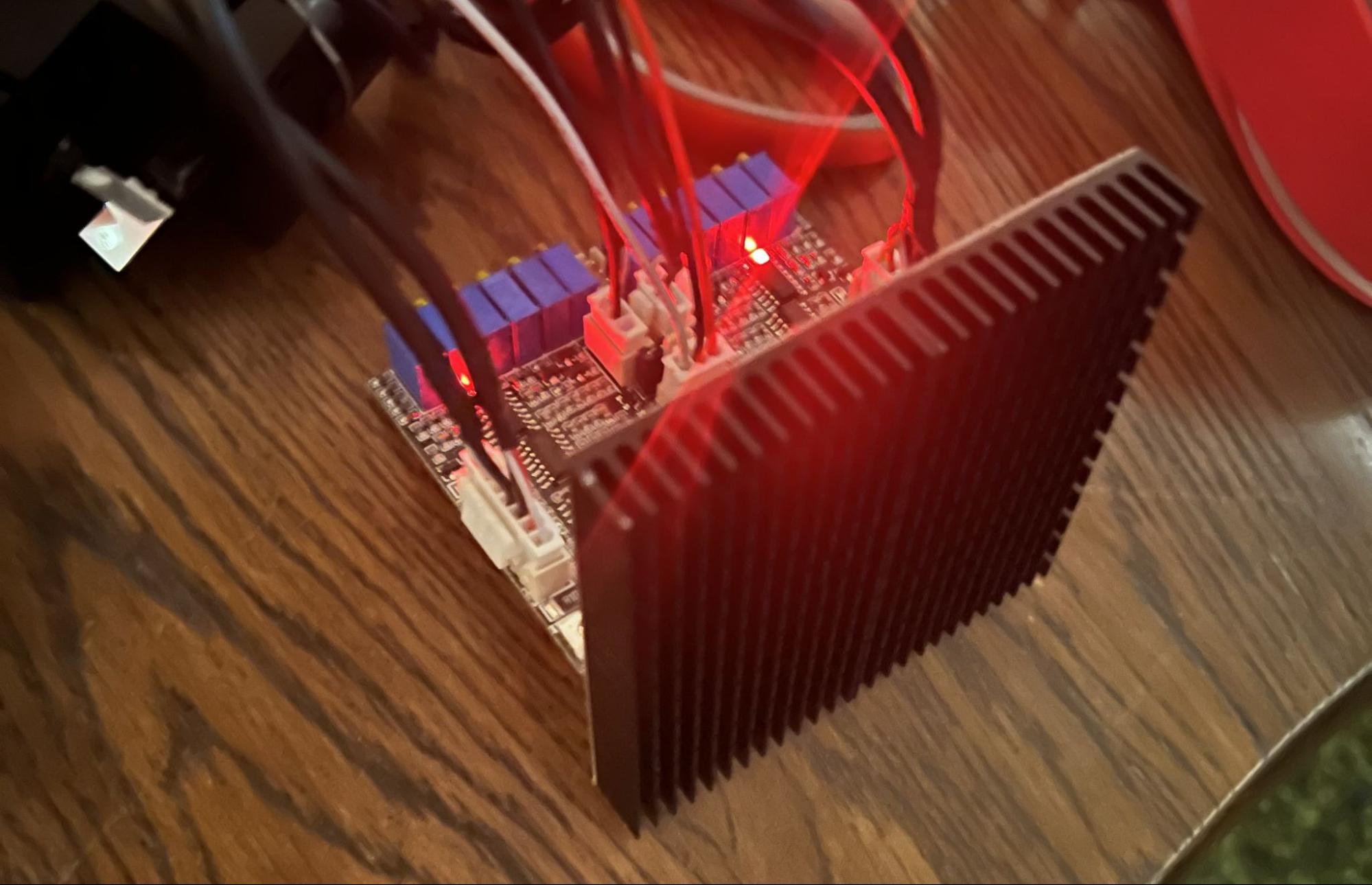
This was a case where the simplest solution was also a good one. I bought an $8 waffle heatsink, attached it to the driver's existing one, and that provided enough additional dissipation that overheating stopped being an issue.
Connecting it to a computer
The last step was getting the galvo talking to my computer. The driver does not take a digital instruction; it takes an analog control signal, a differential voltage per axis, and a computer has no output that produces that. Something has to sit in between and convert.
There is a well-known hack that uses a headphone jack for this, treating the signal meant for each ear as the control voltage for one of the two mirrors. It is a real technique, but two problems make it much harder than it sounds: (Ha! Literally!)
1.Audio outputs are AC coupled. They are built to reproduce changing signals, and a capacitor in the path deliberately blocks any steady DC level. Mirror position, however, is a DC signal - to park the beam on a fixed point you have to hold a steady voltage indefinitely. Through an AC-coupled path, a stationary point decays back toward center. Given how much of what I ended up doing depends on holding the beam still, this alone would have been disqualifying.
2.The voltages do not match. ILDA expects a differential swing of several volts per axis; a headphone jack puts out around a volt, single-ended. Bridging that means building amplification and a differential driver stage before the signal is usable.
Those are the two strongest obstacles rather than the only ones, and between them and the time I had left, I decided it was not worth it. In my opinion, knowing when the do-it-yourself approach is worth its cost in time against the money it saves, and when it is not, is a skill. Instead I spent $100 on a Helios Laser DAC (Digital-to-Analog Converter), which let me plug the galvo into my computer over USB.
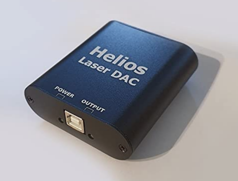
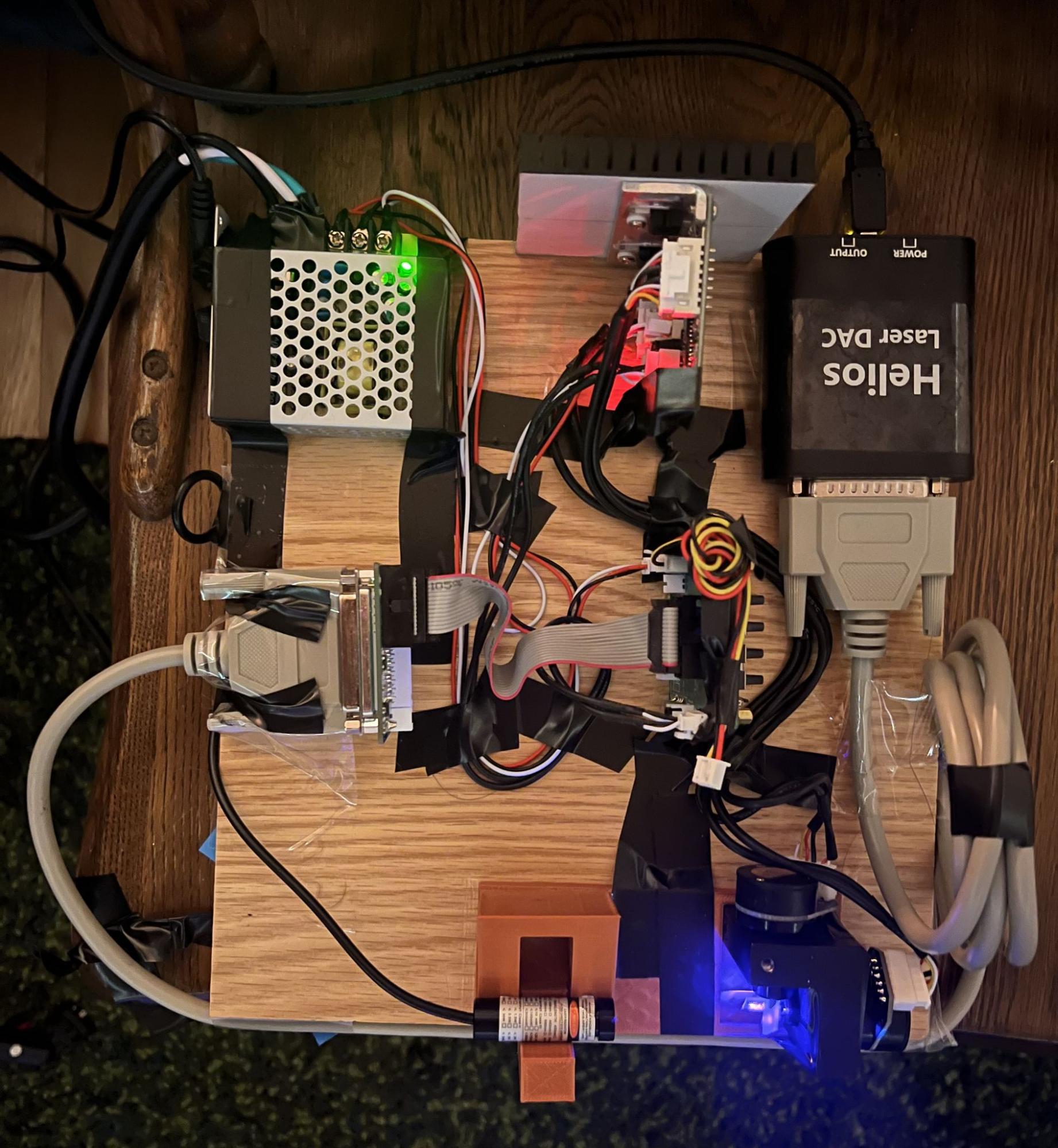
With that, I finally had a working laser galvo. I packed all of the components onto a board of wood, along with a mount that held the laser pointing precisely at the galvo's mirrors, so that I could move and adjust the whole thing easily once it came time to exhibit and so that I could treat my galvo as a finished projection device rather than a pile of wired-together parts.
Driving it with TouchDesigner
Now that I had a laser galvo, what was I actually going to do with it? This is where TouchDesigner comes in.
TouchDesigner is a node-based environment for building real-time interactive media. Instead of writing code, you wire operators together into a network, each operator doing one thing to a stream of data, and the whole network re-evaluates live every frame. Operators are grouped by the kind of data they handle; the family that matters here is CHOPs, which carry channel data - streams of numbers changing over time - which is exactly the shape of the signal a laser scanner wants.
Two of them do the work for this project. The Laser CHOP takes whatever geometry you hand it and formats it as scan data a laser DAC can read. The Laser Device CHOP then identifies the external DAC attached to the machine - the Helios, in my case - and sends that signal out to it. All I had to do was describe the shape I wanted drawn, feed it through those two, and my custom-built galvo took care of the rest.
The node sitting between them in my network is a Switch CHOP, which let me change patterns live during the exhibition. Each pattern is its own small network, and the switch selects which one reaches the DAC without my having to stop anything or rebuild the network in front of an audience.
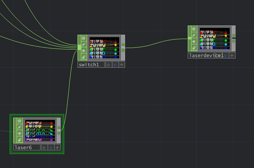
The first thing I ran was an instruction to draw a simple circle:
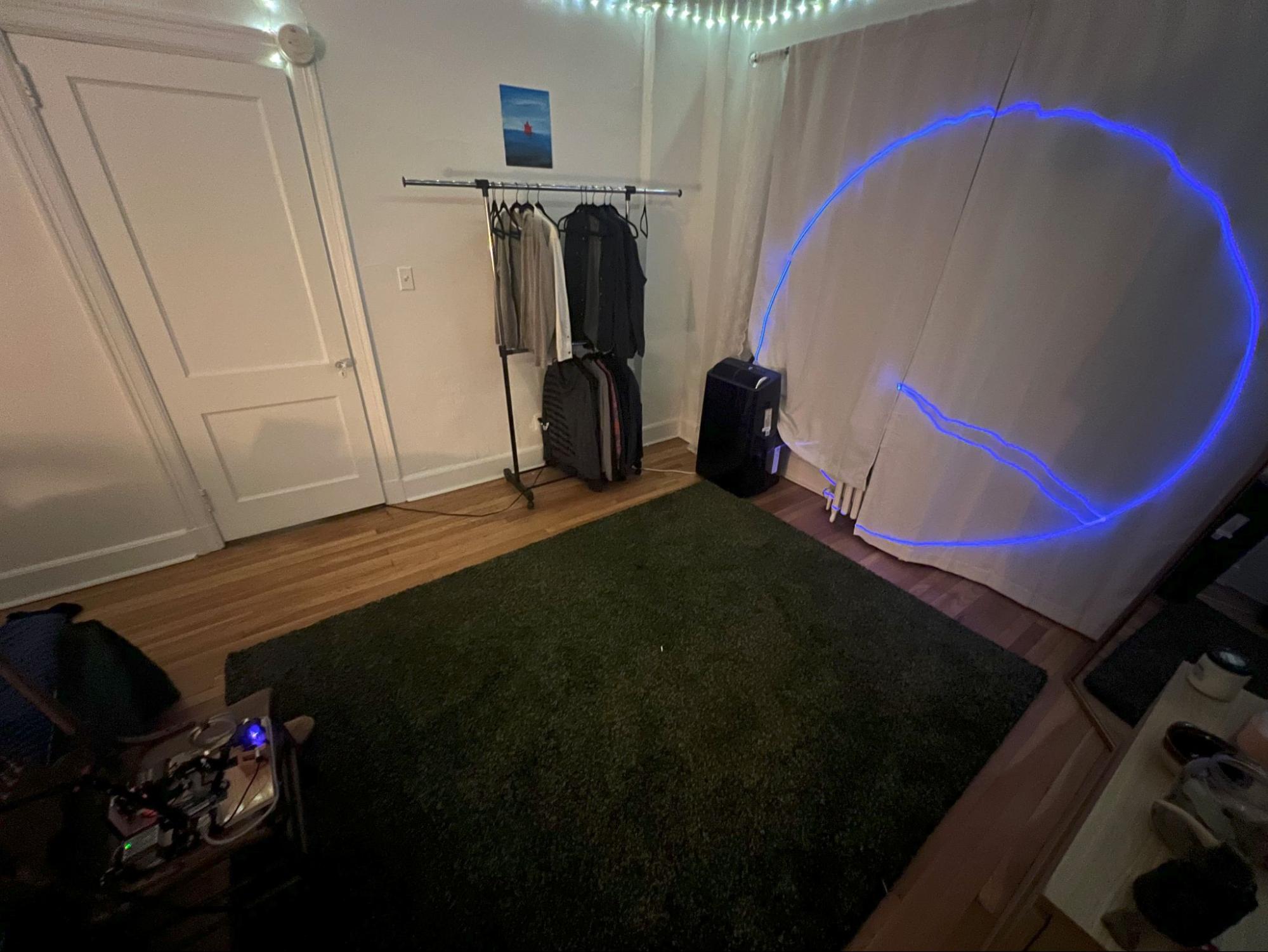
You can see a line running from the edge of the circle into its middle and back out. TouchDesigner was producing points more slowly than the galvo was consuming them, so between one circle and the next the output fell back to its zero position, centering both mirrors and letting the laser dwell there. The fix was to set the Laser CHOP's points per second to match the scanner's own 20,000, so the stream of instructions never ran dry and the galvo was never left idle. That resolved the dwell and everything worked cleanly after it.
The full system
At this point the whole thing was running: a phosphorescent sail blowing in the wind, and generative patterns forming on it out of the overlap between the galvo's shapes and the sail's movement.
From Project to Exhibition
November 2024
For me, creating a full working process is the most important part of a project, and here I had one: a process that lets the wind draw in light. At that point it becomes important to consider the larger context a project sits in. I am very much a believer in science for science's sake and art for art's sake, but it is also important to be a contributor to the worlds of art and science. For research that might mean publishing; for art it might mean exhibiting. These "Behind the Project" sections are themselves an example of bringing a project into the world. If I can share how I make things, it might help someone who wants to use a component of my project, or help inspire them to make something else entirely.
The context for this piece was the exhibition at Tech25, and my goal from here was to make the process as exhibition-worthy as I could: as beautiful, as pointed, and as intuitive a representation of the wind as possible. The first thing I could do was experiment with the patterns I set up in TouchDesigner. What I found fell into two categories.
1: Overlapping patterns
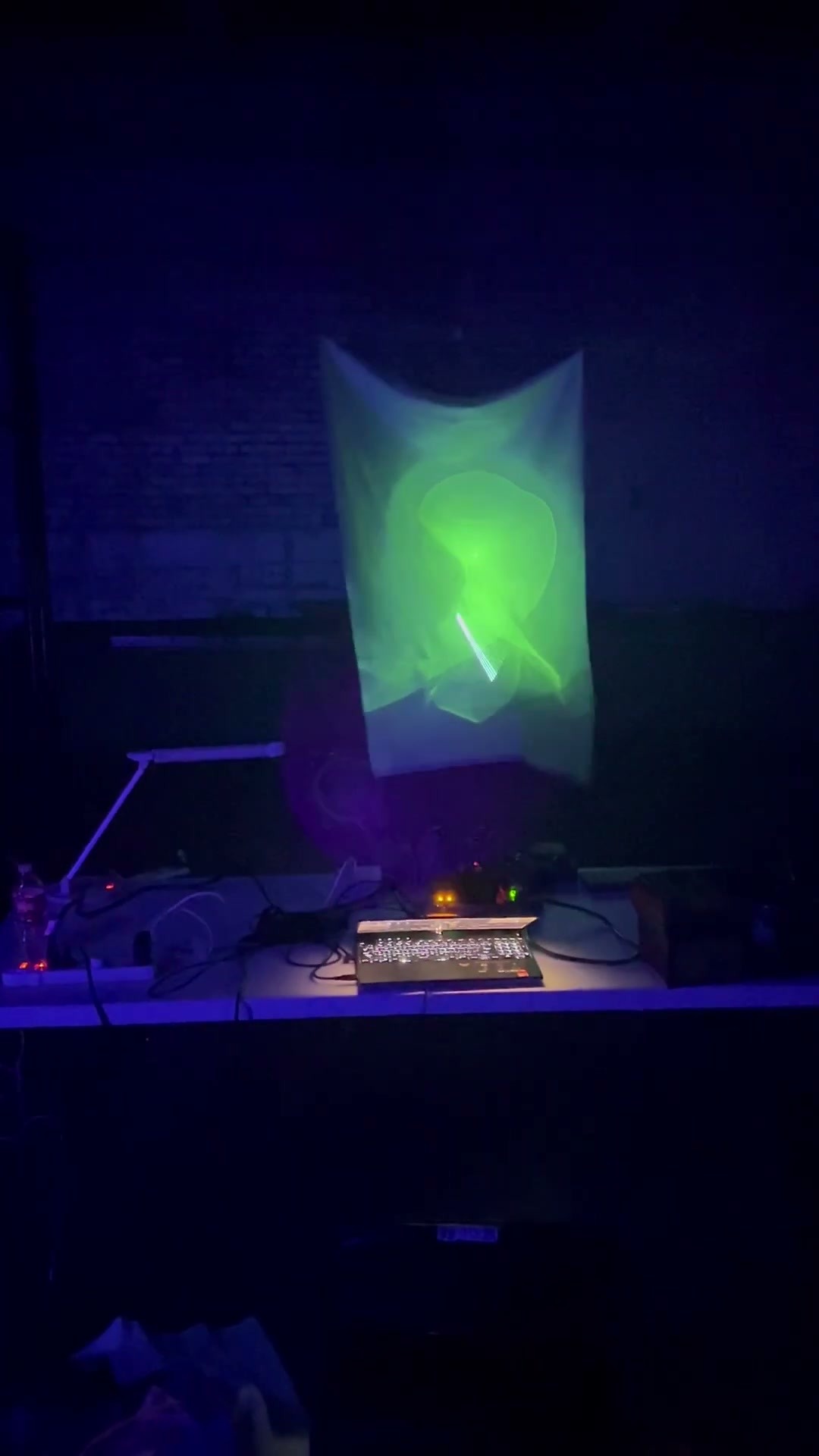
These were some of the most beautiful patterns I made. The galvo runs at full speed, so consecutive passes of the same shape land about a hundredth of a second apart, and consecutive passes therefore land very close to one another on the sail. As the sail moves, those lines overlap at slightly different angles and slightly different positions, producing the flowing, interwoven moiré patterns you see here.
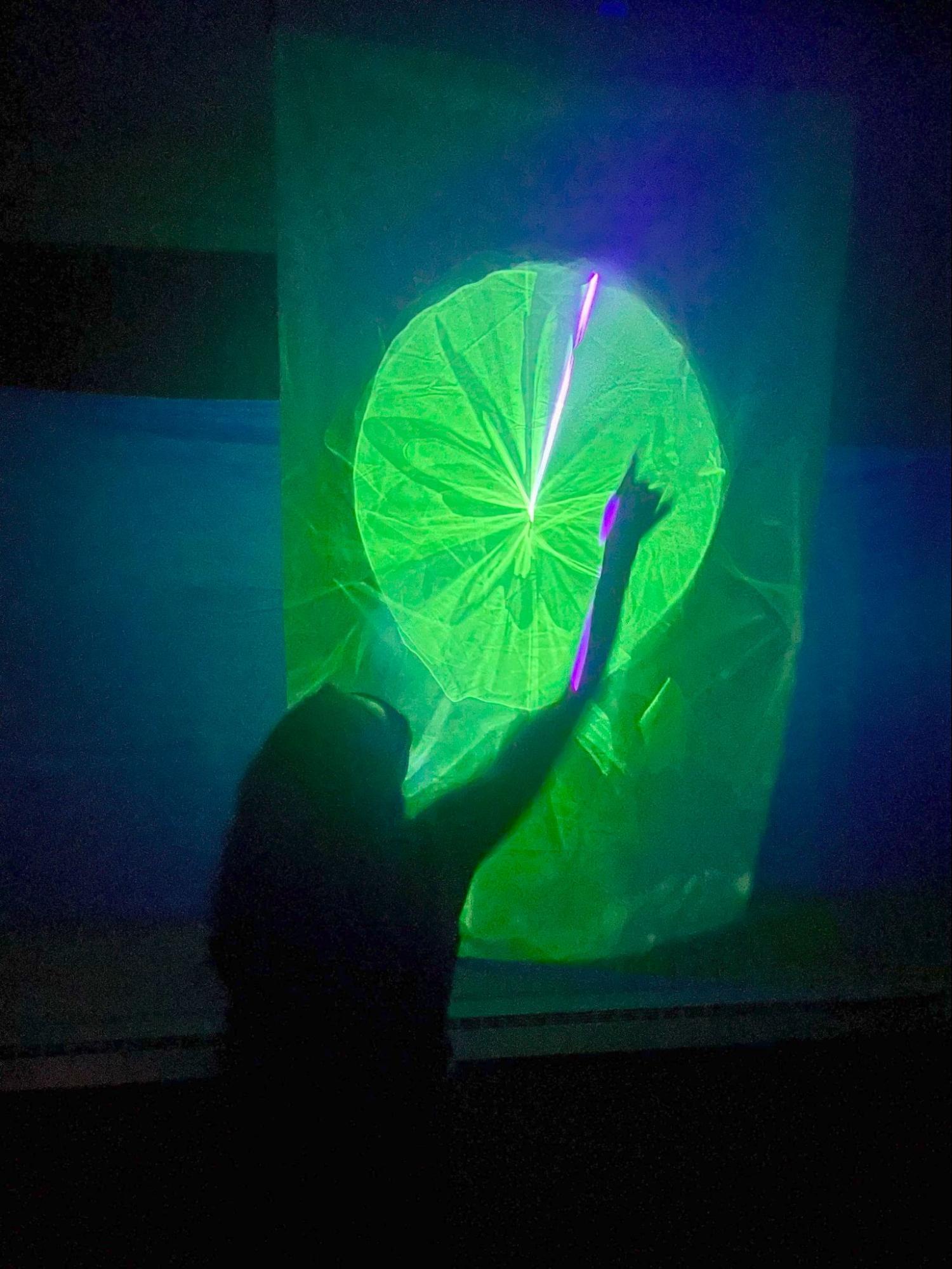
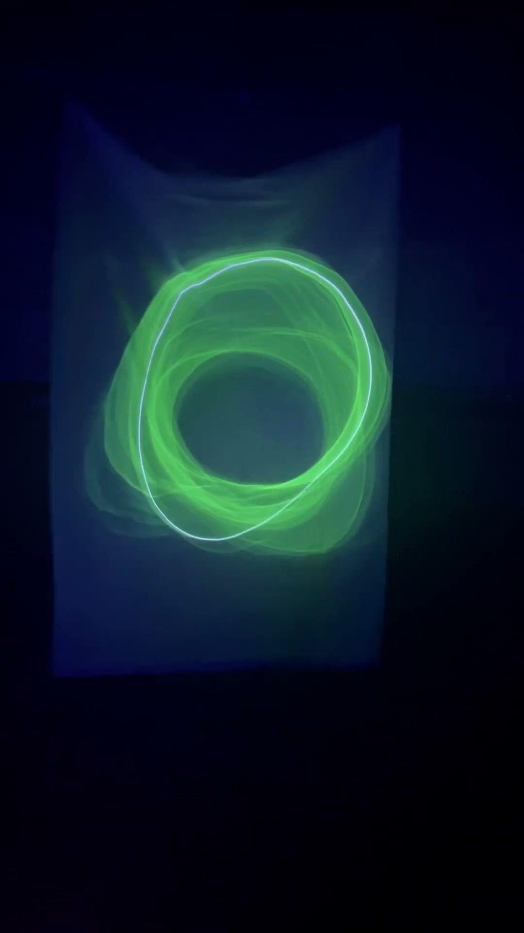
In this mode the laser is read as a continuous shape, since the point is moving faster than the eye can resolve, and the interesting part is how the shape drawn by the galvo and the motion created by the wind interfere with one another. These created organic, complex forms. The patterns generated in this mode read the most as generative art.
2: Synced patterns
These were made by slowing the galvo down enormously, so that instead of being read by the eye as a continuous shape it is visibly a single moving point. Specifically, I synced the period of the pattern the galvo draws to the period of the stable flapping motion I had noticed back in V0. If the sail's period was ten seconds - and it varied with the exact arrangement of sail, fan, and the room they were in - then I set the galvo to take ten seconds to complete one circle, rather than the hundredth of a second it would take at full speed.
The result is that you can read how the sail shifted over the course of its entire ten-second period from how the circle is warped. The galvo is drawing a perfect circle throughout; every deviation you see is the shape of the sail changing under the wind. In the example below, the sail stays fairly even for most of its period except at one point, lined up with the top of the circle, where it folds out of shape and produces that large dent.
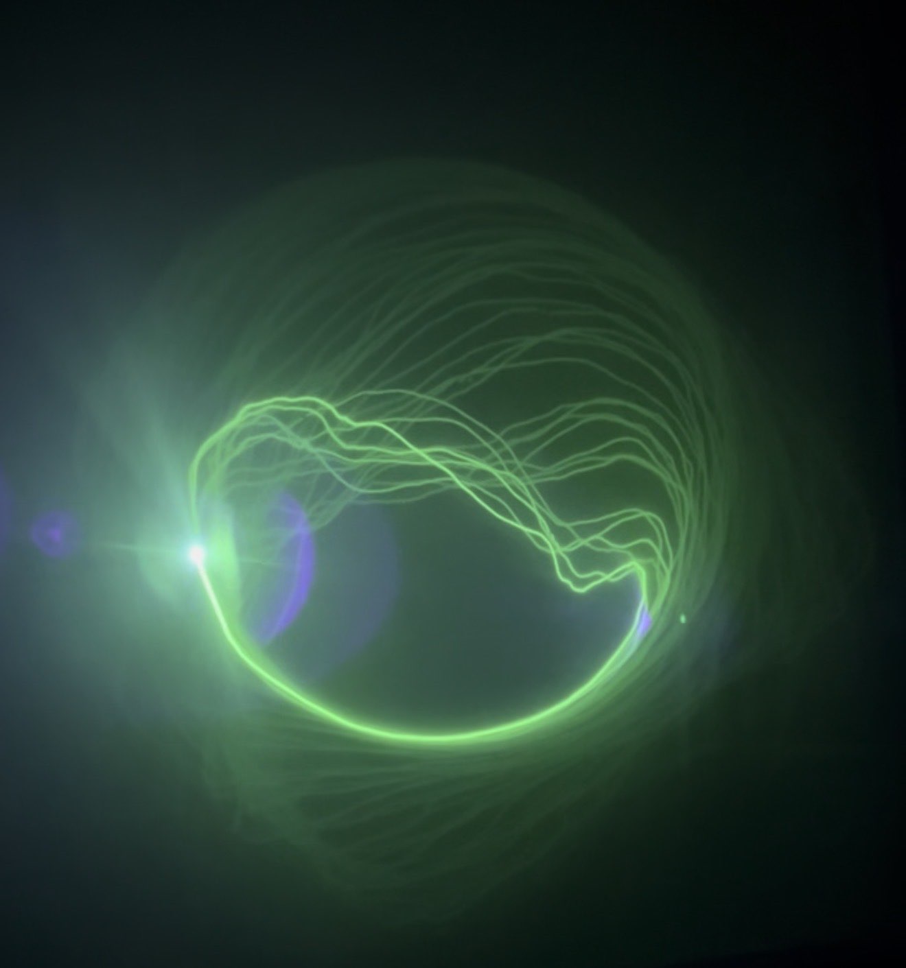
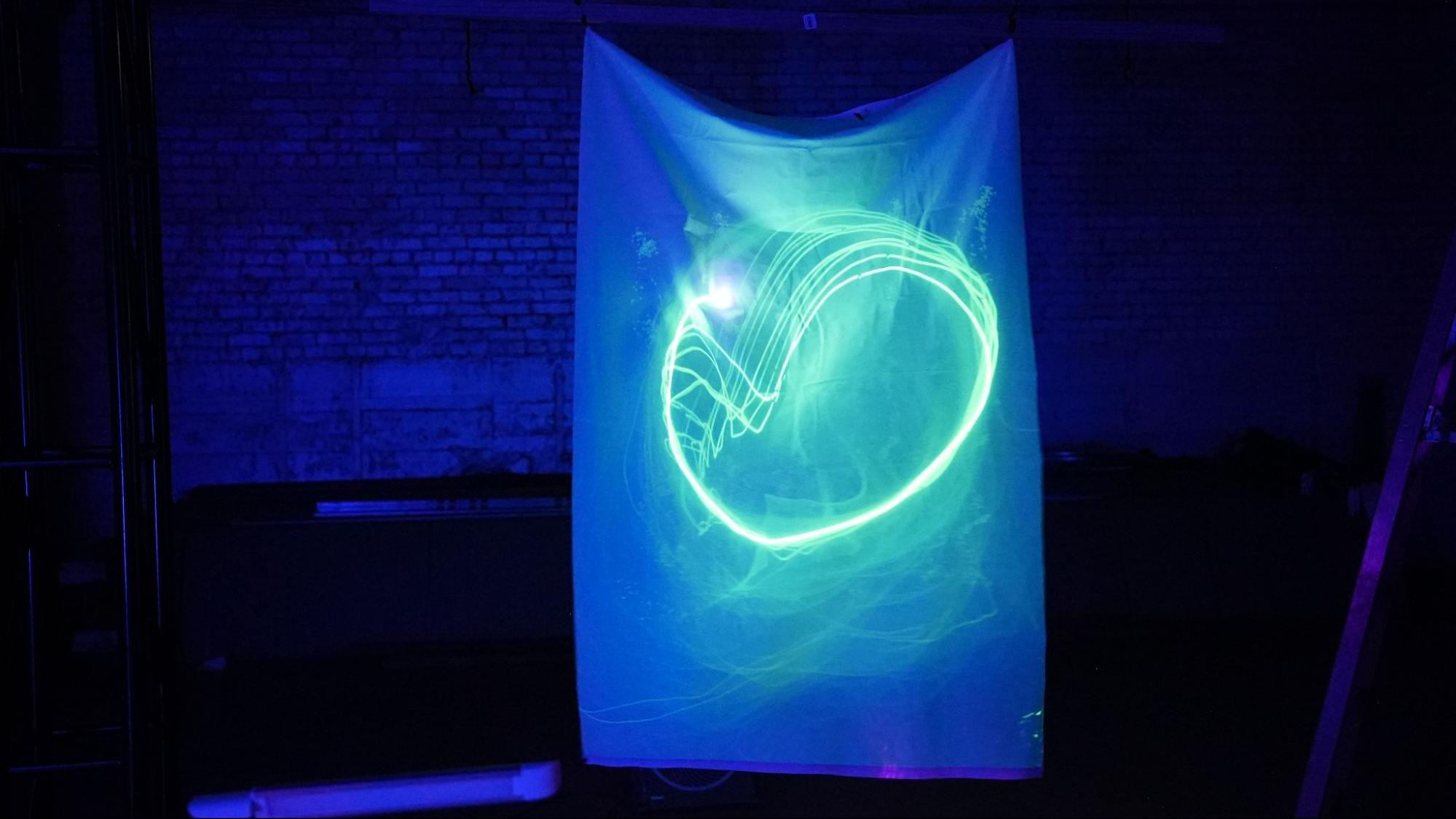
These also show trends between one period and the next. Across successive periods the dent slowly grows and shifts, for two reasons:
1.The period's duration changes. Even when I set the drawn shape's period precisely against the sail's, the sail's flapping period drifts slowly over time. This might be caused by subtle shifts in the wind and pressure in the room, or by the sail itself settling.
2.The shape the sail is blown into changes. Even when the sail is holding the same period, the shape being traced still evolves across periods. Again, this could come from the sail or the structure it hangs from settling, or from the air currents in the room.
Where the overlapping patterns produced the most artistic output, these produced the most descriptive. The shape tells you something specific about the movement of the sail, and by extension about the wind - the dent in the circle, and the drift of that dent from one period to the next.
A grid of stationary points
The single large circle is one kind of synced pattern. However, it is fairly limited in what it can tell you about the shape the sail is being blown into. The dent shows you which moment in the period that part of the sail is at its most deformed, but it is hard to extract anything more specific than that. To get more meaningful data out of Lightsail I built a second synced pattern: a grid of stationary points.
Before I built the galvo, I had first noticed the stable period in the sail's motion by simply pointing the fixed laser at it and watching it trace out a repeated blob. That tells you about the movement of one small area of the sail, but not much about the sail overall. With the galvo, I could distribute a 5x5 grid of those points across the surface. Each one behaves exactly like the single stationary dot, and spread across the sail, I would be gaining the local info of the single stationary dot, but for each area of the entire sail rather than the single sampled spot.
The laser can only be in one place at a time, but the galvo is fast enough to move between 25 positions so rapidly that it appears to be in all of them at once.
This is where the blanking limitation became a problem. With no way to switch the laser off, everything I draw is a continuous line, and if I tell the laser to cycle rapidly between 25 points it spends most of its time traveling between those points - and all of that travel gets drawn too. Instead of a grid of 25 stationary dots I would get a tangle of lines anchored at those 25 positions. What I wanted was 25 pencils held still, with the sail working as paper moving underneath them and recording the relative motion. The connecting lines would ruin that.
My first solution was to have the laser dwell at each of the 25 points for a twenty-fifth of a second. That dwell is long enough that the laser spends far more time sitting on each dot than traveling between them.
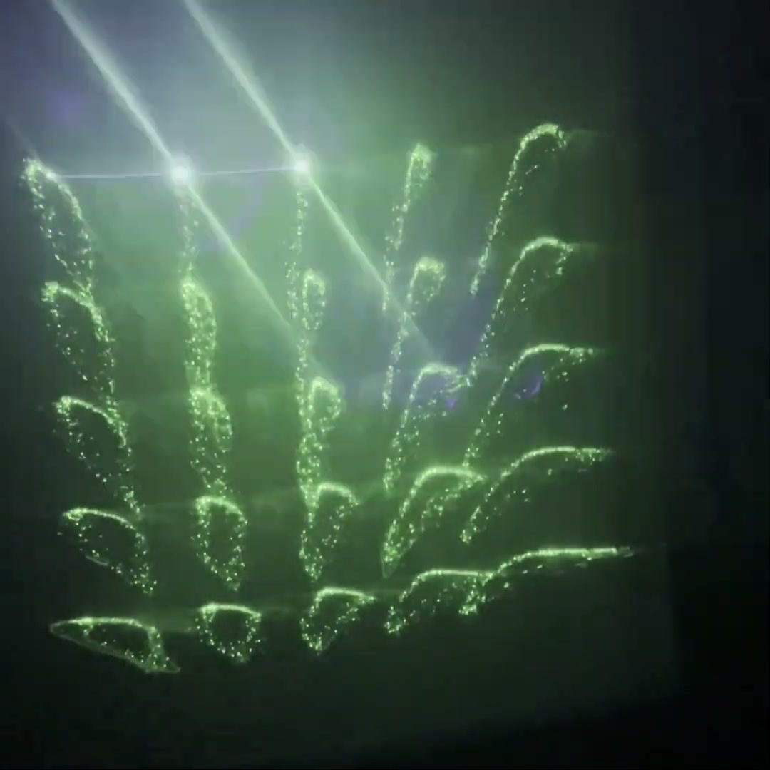
But this introduced a new problem. Twenty-five dots at a twenty-fifth of a second each means every individual dot is marked only once per second, and the sail moves enough in that second that the blobs stop reading as continuous. Instead of the solid blob I got from the fully stationary laser, I got a dotted outline of a blob, which is less attractive. The strobing was unpleasant to look at as well, and the lines connecting each blob to the next were still somewhat visible.
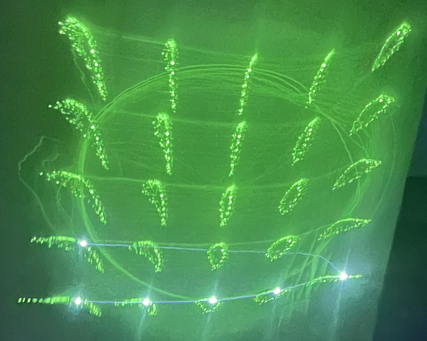
Left: a single stationary point, exposed continuously, leaves a solid trace. Right: with the laser cycling through all 25 points, each one is struck only once per second, and the same trace comes out as a dotted outline.
My second solution was to stop cycling the galvo between the points at all. Instead it holds at one of the 25 points for a full flapping period before jumping to the next point in line. Building the complete field this way takes much longer - on the order of a few minutes - but amortized over a span longer than that, the laser still spends the same total amount of time at each of the 25 positions as in my first solution. The difference is that it now jumps between dots once per period, roughly every ten seconds, rather than 25 times per second. The blanking problem is not solved, but the laser now spends so little of its time on the paths between points that those paths never meaningfully excite the phosphor, and since a full blob is drawn before the laser moves on to the next blob, the blobs appear continuous rather than dotted.
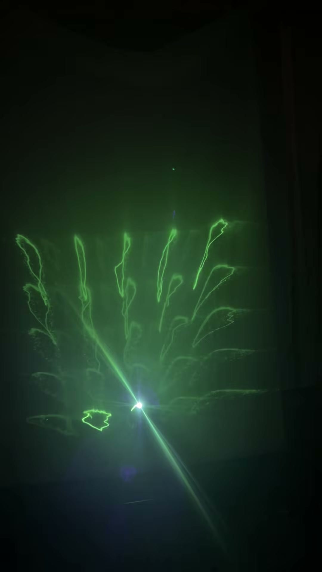
I generally prefer this version, but it isn't perfect: the blobs that have not been marked recently are seriously faded by the time the field is complete. Not so faded that you cannot read their form, but enough to create a visual asymmetry across the grid. In exchange, the blobs themselves are far more clearly defined. In the video above you can see that when I turned the fan's power down, partway through the second blob of the middle row, the blobs immediately became smaller. The fact that this change is so evident is a great sign that this version is able to meaningfully convey information about the behavior of the sail and, fundamentally, the wind.
So what does the 5x5 grid actually show?
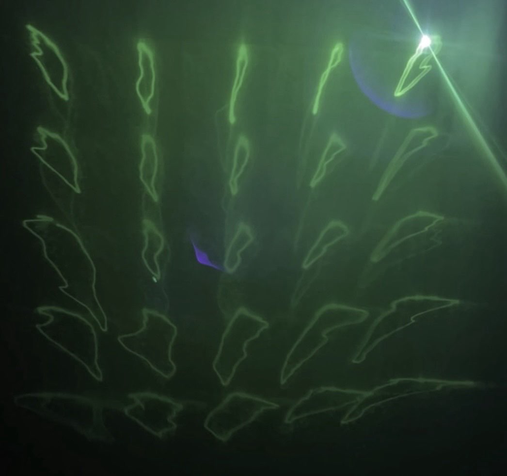
A field of related blobs, each one representing the motion of the sail in that area. One important caveat is that some of the warping is a straightforward result of perspective: all 25 blobs are drawn by a beam originating from the same point, so the ones on the left carry a left-leaning warp, and the same holds at every other edge. Setting that aside and looking at the actual shapes, you can see similar dents and divots slowly emerge and then get subsumed as you move across the sail, showing how different parts of the fabric are related but not identical in their motion. This is not behavior that you would get from perspective warping, which should change the angles and lengths of the sides of the blob but not its fundamental structure. Cases where we see the structure shift across blobs are the result of the wind affecting different parts of the sail in different manners.
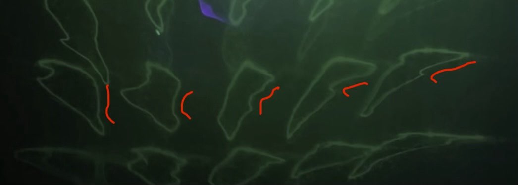
1/2: red lines to emphasize contours shifting and evolving across adjacent blobs in the field
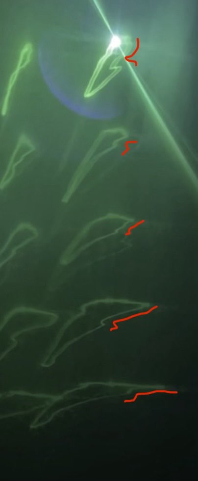
2/2: red lines to emphasize contours shifting and evolving across adjacent blobs in the field
This project is another example of in-place measurement, like Ball and Line, where I measure features of a thing upon the thing itself. The sail is used both as the measuring device, in that it responds to the motion of the wind, and as the recording device, in that it displays the marks you can use to read the motion of the wind.
The exhibition
For the exhibition itself, it was important to be able to freely swap between TouchDesigner patterns. I stayed on the overlapping patterns, which are the most visually striking, when I was not standing there to discuss the piece, and moved to the synced patterns when I was there to explain why those patterns conveyed something interesting.
Beyond that, setup was mostly a matter of making sure I had enough space and working out the lighting. Low light was best for the piece, and I settled on low blue lights to complement the color of the laser itself. It came together well.
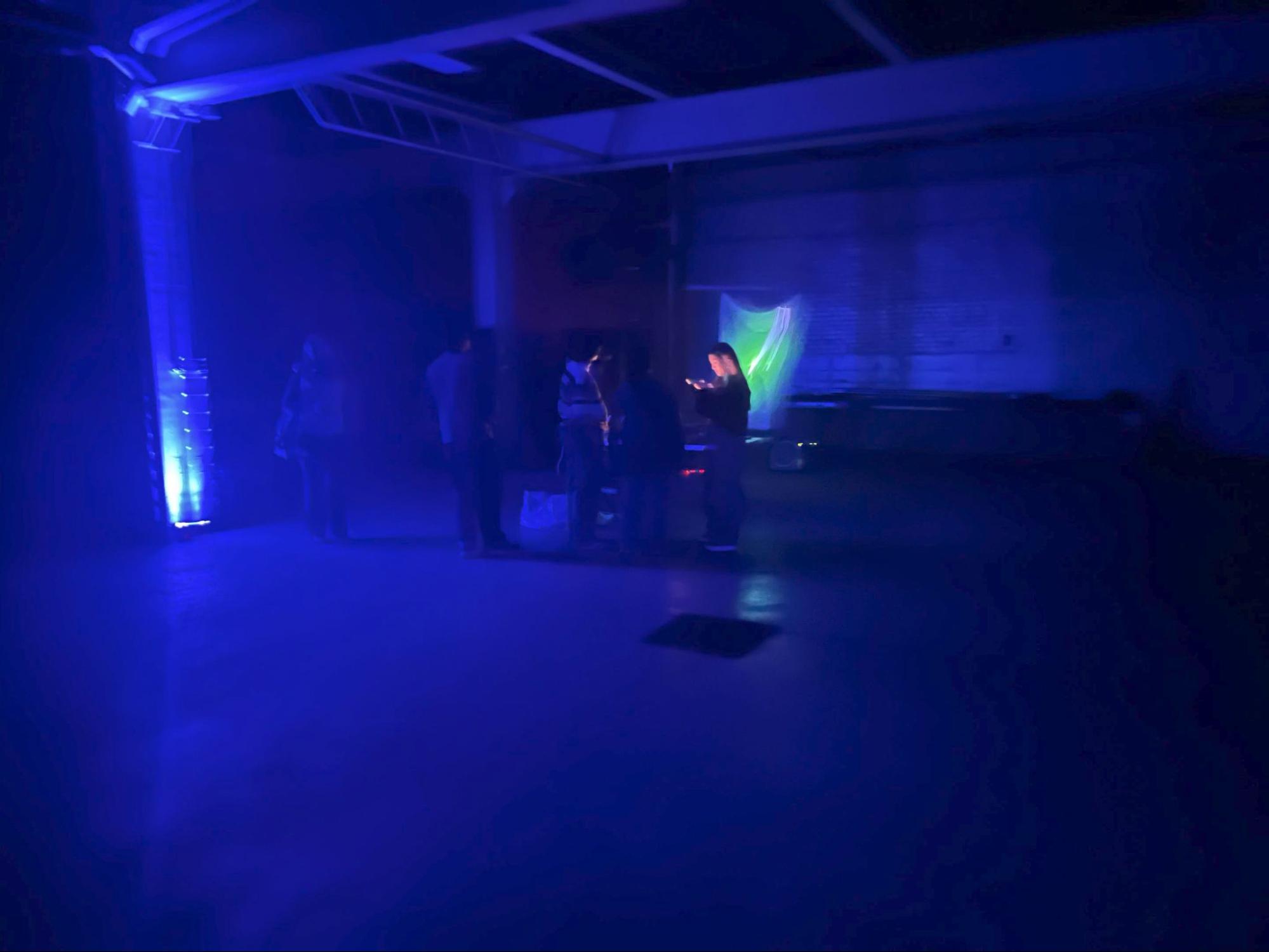
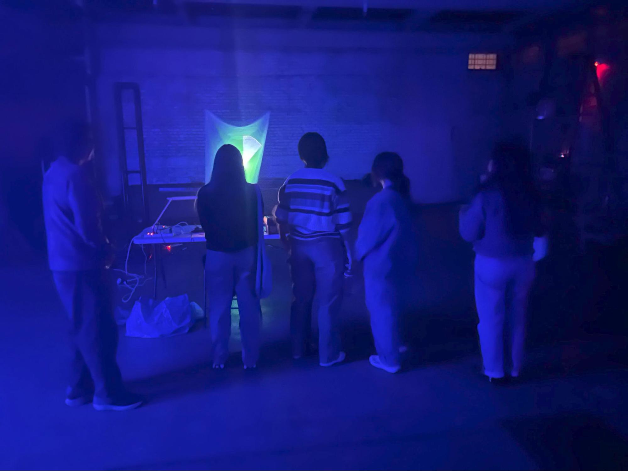
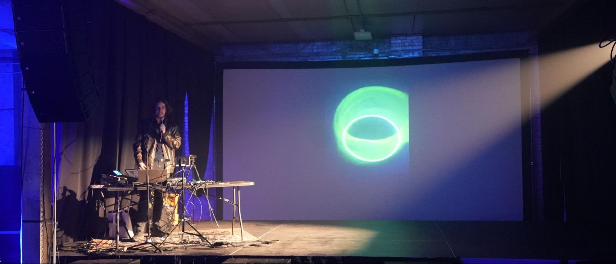
As part of the exhibition I also gave a talk on the mechanics behind Lightsail, the core of which became this "Behind the Project" section!
What It Became
November 2024
The original proof of concept was a fan, a sheet of glow-in-the-dark fabric, and a laser pointer held still. Once I had it functioning, it revealed something I had not gone looking for: the sail flaps with a stable period, and the same closed circuit gets traced again and again. But a fixed point can only ever report on one small patch of fabric, and the result read more like a demonstration than a piece.
Building the galvanometer is what really made the piece. Assembling a custom galvo out of Amazon components, getting it to stop cooking itself, and driving it from TouchDesigner through a DAC saved me about $800. Once I had a fully functional galvo, I began to explore different sorts of patterns I could make with it, and eventually discovered two categories. Run the galvo at full speed and the wind smears each pass of the shape across the last one, producing dense moiré forms that are the most beautiful thing the setup makes. Slow it down until its period matches the sail's and the same machine becomes a measuring instrument: a perfect circle comes back dented exactly where the fabric folds, and a 5x5 grid of held points returns a field of blobs that maps the varied movements of the sail throughout its surface. Ultimately, the sail ends up being both the thing being measured and the surface the measurement is written on.
The project is on GitHub, but most of this project is physical - the galvo build, the laser mount, the sail and fan arrangement - so the repository mostly holds the TouchDesigner files that drive the patterns.
Kirkland Gallery, Cambridge, September 2025